- Dynamic parameters of the coolant
- Thermal calculation of heating: general procedure
- Program overview
- What is included in the calculation?
- Determination of pressure losses in pipes
- The procedure for calculating the hydraulic parameters of heating
- Determining the optimal pipe diameter
- Accounting for local resistance in the trunk
- Initial conditions of the example
- Buy TEPLOOV
- Calculation of the hydraulics of heating channels
- Number of pump speeds
- Calculation steps
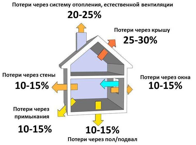
- Heat loss calculation
- Temperature conditions and selection of radiators
- Hydraulic calculation
- Boiler selection and some economics
- Heating system hydraulics example
- Accurate heat load calculations
- Calculation for walls and windows
- Ventilation calculation
Dynamic parameters of the coolant
We proceed to the next stage of calculations - analysis of the consumption of the coolant. In most cases, the apartment heating system differs from other systems - this is due to the number of heating panels and the length of the pipeline. Pressure is used as an additional “driving force” for flow vertically through the system.
In private one- and multi-storey houses, old panel apartment buildings, high-pressure heating systems are used, which allows transporting the heat-releasing substance to all sections of the branched, multi-ring heating system and raising water to the entire height (up to the 14th floor) of the building.
On the contrary, an ordinary 2- or 3-room apartment with autonomous heating does not have such a variety of rings and branches of the system, it includes no more than three circuits.
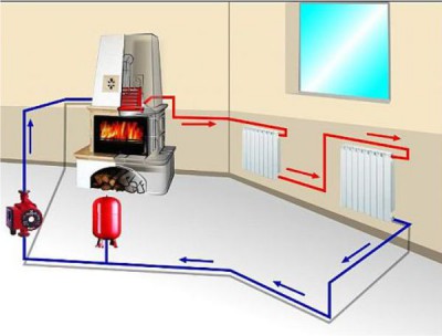
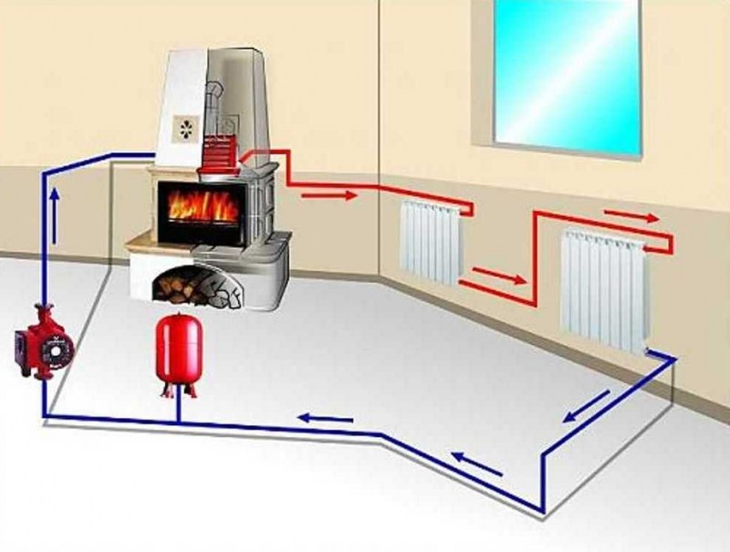
This means that the transportation of the coolant occurs using the natural process of water flow. But it is also possible to use circulation pumps, heating is provided by a gas / electric boiler.
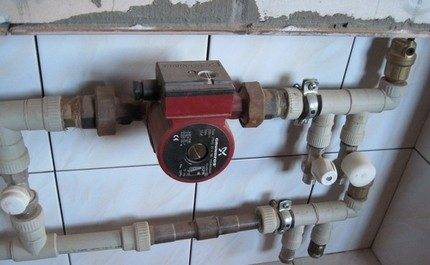
We recommend using a circulation pump for space heating over 100 m2. You can mount the pump both before and after the boiler, but usually it is put on the “return” - lower carrier temperature, less airiness, longer pump life
Specialists in the field of design and installation of heating systems define two main approaches in terms of calculating the volume of coolant:
- According to the actual capacity of the system. All volumes of cavities without exception are summed up, where the flow of hot water will flow: the sum of individual sections of pipes, sections of radiators, etc. But this is a rather laborious option.
- Boiler power. Here, the opinions of experts differed very much, some say 10, others 15 liters per unit of boiler power.
From a pragmatic point of view, one must take into account the fact that probably the heating system will not only supply hot water for the room, but also heat water for the bath / shower, washbasin, sink and dryer, and maybe for a hydromassage or jacuzzi. This option is faster.
Therefore, in this case, we recommend setting 13.5 liters per unit of power. Multiplying this number by the boiler power (8.08 kW), we get the estimated volume of water mass - 109.08 liters.
The calculated coolant velocity in the system is exactly the parameter that allows you to select a specific pipe diameter for the heating system.
It is calculated using the following formula:
V = (0.86 * W * k) / t-to,
where:
- W - boiler power;
- t is the temperature of the supplied water;
- to is the water temperature in the return circuit;
- k - boiler efficiency (0.95 for a gas boiler).
Substituting the calculated data into the formula, we have: (0.86 * 8080 * 0.95) / 80-60 \u003d 6601.36 / 20 \u003d 330 kg / h. Thus, in one hour, 330 liters of coolant (water) moves in the system, and the capacity of the system is about 110 liters.
Thermal calculation of heating: general procedure
The classical thermal calculation of a heating system is a summary technical document that includes the required step-by-step standard calculation methods.
But before studying these calculations of the main parameters, you need to decide on the concept of the heating system itself.
The heating system is characterized by forced supply and involuntary removal of heat in the room.
The main tasks of calculating and designing a heating system:
- most reliably determine heat losses;
- determine the amount and conditions for the use of the coolant;
- select the elements of generation, movement and heat transfer as accurately as possible.
When building a heating system, it is necessary to initially collect various data about the room / building where the heating system will be used. After performing the calculation of the thermal parameters of the system, analyze the results of arithmetic operations.
Based on the data obtained, the components of the heating system are selected with subsequent purchase, installation and commissioning.
Heating is a multi-component system for ensuring the approved temperature regime in a room/building. It is a separate part of the communications complex of a modern residential building
It is noteworthy that the indicated method of thermal calculation makes it possible to accurately calculate a large number of quantities that specifically describe the future heating system.
As a result of the thermal calculation, the following information will be available:
- number of heat losses, boiler power;
- the number and type of thermal radiators for each room separately;
- hydraulic characteristics of the pipeline;
- volume, speed of the heat carrier, power of the heat pump.
Thermal calculation is not a theoretical outline, but quite accurate and reasonable results, which are recommended to be used in practice when selecting the components of a heating system.
Program overview
For the convenience of calculations, amateur and professional programs for calculating hydraulics are used.
The most popular is Excel.
You can use the online calculation in Excel Online, CombiMix 1.0, or the online hydraulic calculator. The stationary program is selected taking into account the requirements of the project.


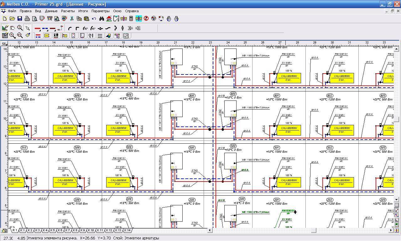
The main difficulty in working with such programs is ignorance of the basics of hydraulics. In some of them, there is no decoding of formulas, the features of branching of pipelines and the calculation of resistances in complex circuits are not considered.
- HERZ C.O. 3.5 - makes a calculation according to the method of specific linear pressure losses.
- DanfossCO and OvertopCO can count natural circulation systems.
- "Flow" (Flow) - allows you to apply the calculation method with a variable (sliding) temperature difference along the risers.
You should specify the data entry parameters for temperature - Kelvin / Celsius.
What is included in the calculation?
Before starting the calculations, you should perform a series of graphic
ski actions (often a special program is used for this).Hydraulic calculation involves determining the heat balance indicator of the room in which the heating process takes place.
To calculate the system, the longest heating circuit is considered, including the largest number of devices, fittings, control and shut-off valves and the largest pressure drop in height. The following quantities are included in the calculation:
- pipeline material;
- the total length of all sections of the pipe;
- pipeline diameter;
- pipeline bends;
- resistance of fittings, fittings and heating devices;
- the presence of bypasses;
- coolant fluidity.
To take into account all these parameters, there are specialized computer programs, such as NTP Truboprovod, Oventrop CO, HERZ S.O. version 3.5. or many of their analogues, facilitating calculations for specialists.
They contain the necessary reference data for each element of the heat supply system and allows you to automate the calculation itself. However, the user will have to do the lion's share of the work, determine the key points and enter all the data for the calculation and features of the pipeline scheme. For convenience, it is advisable to gradually fill in a pre-created form in MS excel.
Making the right calculations in terms of overcoming resistance is the most time-consuming, but neo
A necessary step in the design of water-type heating systems.
Determination of pressure losses in pipes
The pressure loss resistance in the circuit through which the coolant circulates is determined as their total value for all individual components. The latter include:
- losses in the primary circuit, denoted as ∆Plk;
- local heat carrier costs (∆Plm);
- pressure drop in special zones, called “heat generators” under the designation ∆Ptg;
- losses inside the built-in heat exchange system ∆Pto.
After summing these values, the desired indicator is obtained, which characterizes the total hydraulic resistance of the system ∆Pco.
In addition to this generalized method, there are other ways to determine the head loss in polypropylene pipes. One of them is based on a comparison of two indicators tied to the beginning and end of the pipeline. In this case, the pressure loss can be calculated by simply subtracting its initial and final values, determined by two pressure gauges.
Another option for calculating the desired indicator is based on the use of a more complex formula that takes into account all the factors that affect the characteristics of the heat flux. The ratio given below primarily takes into account the loss of liquid head due to the long length of the pipeline.
- h is the liquid head loss, measured in meters in the case under study.
- λ is the coefficient of hydraulic resistance (or friction), determined by other calculation methods.
- L is the total length of the serviced pipeline, which is measured in running meters.
- D is the internal size of the pipe, which determines the volume of the coolant flow.
- V is the fluid flow rate, measured in standard units (meter per second).
- The symbol g is the free fall acceleration, which is 9.81 m/s2.
Pressure loss occurs due to fluid friction on the inner surface of the pipes
Of great interest are the losses caused by the high coefficient of hydraulic friction. It depends on the roughness of the inner surfaces of the pipes.The ratios used in this case are valid only for tubular blanks of a standard round shape. The final formula for finding them looks like this:
- V - the speed of movement of water masses, measured in meters / second.
- D - inner diameter, which determines the free space for the movement of the coolant.
- The coefficient in the denominator indicates the kinematic viscosity of the liquid.
The latter indicator refers to constant values and is found according to special tables published in large quantities on the Internet.
The procedure for calculating the hydraulic parameters of heating
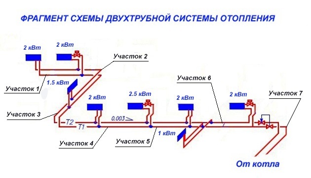
Heating on the plan of the house
At the first stage of calculating the parameters of the heating system, a preliminary diagram should be drawn up, which indicates the location of all components. Thus, the total length of the mains is determined, the number of radiators, the volume of water, as well as the characteristics of the heating devices are calculated.
How to make a hydraulic calculation of heating without experience in such calculations? It should be remembered that for autonomous heat supply it is important to choose the right pipe diameter. It is from this stage that the calculations should begin.
Determining the optimal pipe diameter
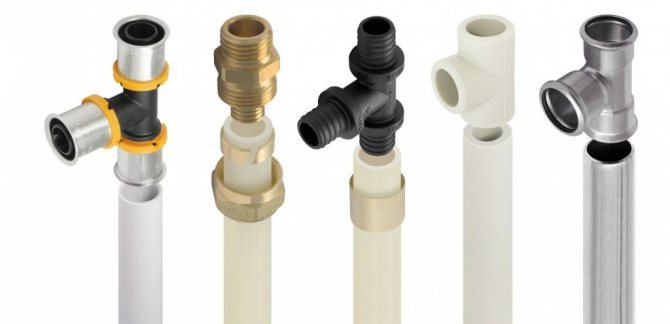
Types of pipes for heating
The most simplified hydraulic calculation of the heating system includes only the calculation of the cross section of pipelines. Often, when designing small systems, they do without it. To do this, take the following parameters of pipe diameters, depending on the type of heat supply:


- Open scheme with gravitational circulation. Pipes with a diameter of 30 to 40 mm. Such a larger cross section is necessary to reduce losses due to friction of water on the inner surface of the mains;
- Closed system with forced circulation. The cross section of pipelines varies from 8 to 24 mm. The smaller it is, the greater the pressure will be in the system and, accordingly, the total volume of the coolant will decrease. But at the same time, hydraulic losses will increase.
If there is a specialized program for the hydraulic calculation of the heating system, it is enough to fill in the data on the technical characteristics of the boiler and transfer the heating scheme. The software package will determine the optimal pipe diameter.
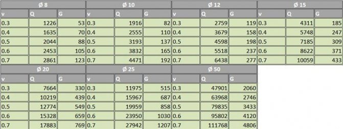
Table for selection of internal diameter of pipelines
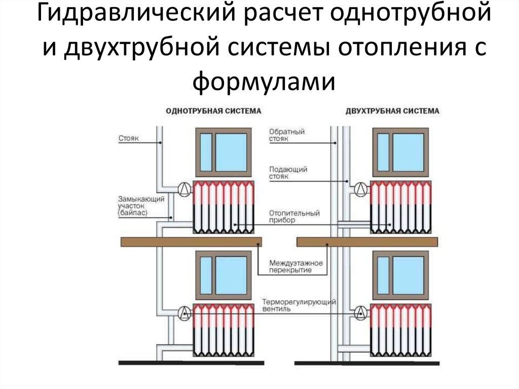
The received data can be checked independently. The procedure for performing a hydraulic calculation of a two-pipe heating system manually when calculating the diameter of pipelines is to calculate the following parameters:
- V is the speed of water movement. It should be in the range from 0.3 to 0.6 m / s. Determined by the performance of pumping equipment;
- Q is the heat flux. This is the ratio of the amount of heat passing over a certain period of time - 1 second;
- G - water flow. Measured in kg/hour. Directly depends on the diameter of the pipeline.
In the future, to perform a hydraulic calculation of water heating systems, you will need to find out the total volume of the heated room - m³. Let's assume that this value for one room is 50 m³. Knowing the power of the heating boiler (24 kW), we calculate the final heat flow:
Q=50/24=2.083 kW
table of water consumption depending on the diameter of the pipe
Then, to select the optimal pipe diameter, you need to use the table data compiled when performing a hydraulic calculation of the heating system in Excel.
In this case, the optimal inner diameter of the pipe in a particular section of the system will be 10 mm.
In the future, to perform an example of a hydraulic calculation of a heating system, you can find out the approximate water flow, which will whistle from the diameter of the pipe.
Accounting for local resistance in the trunk
Example of hydraulic calculation of heating
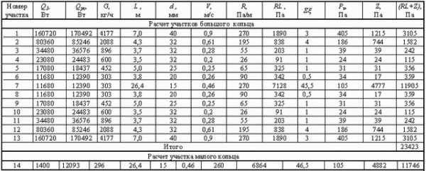
An equally important step is the calculation of the hydraulic resistance of the heating system on each section of the highway. To do this, the entire heat supply scheme is conditionally divided into several zones. It's best to do the calculations for every room in the house.
The following quantities will be needed as initial data for entering into the program for the hydraulic calculation of the heating system:
- The length of the pipe on the site, lm;
- Line diameter. The calculation order is described above;
- Required flow rate. It also depends on the diameter of the pipe and the power of the circulation pump;
- Reference data specific to each type of manufacturing material - friction coefficient (λ), friction losses (ΔР);
- The density of water at a temperature of +80°C will be 971.8 kg/m³.
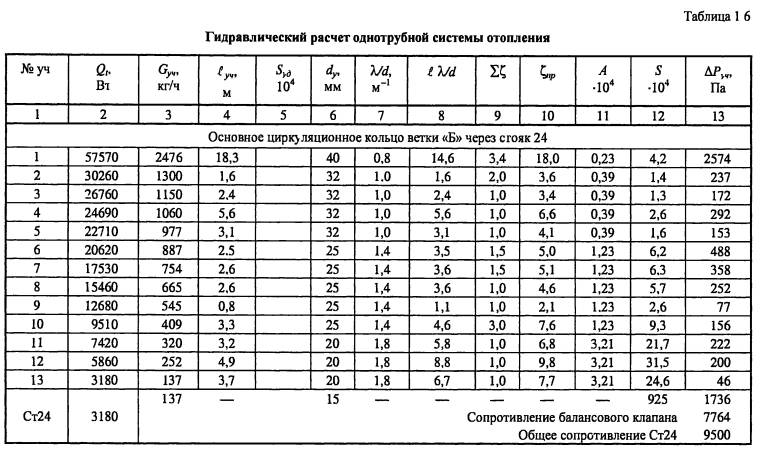
Knowing these data, it is possible to make a simplified hydraulic calculation of the heating system. The result of such calculations can be seen in the table. When carrying out this work, it must be remembered that the smaller the selected heating area, the more accurate the data of the general parameters of the system will be. Since it will be difficult to make a hydraulic calculation of heat supply the first time, it is recommended to carry out a series of calculations for a certain pipeline interval. It is desirable that it contains as few additional devices as possible - radiators, valves, etc.
Initial conditions of the example
For a more concrete explanation of all the details of the hydraulic miscalculation, let's take a specific example of an ordinary dwelling.We have a classic 2-room apartment in a panel house with a total area of 65.54 m2, which includes two rooms, a kitchen, a separate toilet and bathroom, a double corridor, a double balcony.
After commissioning, we received the following information regarding the readiness of the apartment. The described apartment includes walls made of monolithic reinforced concrete structures treated with putty and soil, windows made of a profile with two chamber glasses, tyrso-pressed interior doors, and ceramic tiles on the bathroom floor.
A typical panel 9-storey building with four entrances. There are 3 apartments on each floor: one 2-room apartment and two 3-room apartments. The apartment is located on the fifth floor
In addition, the presented housing is already equipped with copper wiring, distributors and a separate shield, gas stove, bathroom, washbasin, toilet bowl, heated towel rail, sink.
And most importantly, there are already aluminum heating radiators in the living rooms, bathroom and kitchen. The question regarding pipes and the boiler remains open.
Buy TEPLOOV
Hightech LLC supplies software products of the TEPLOOV complex, being a regional dealer. The working version of the programs is transferred under a letter of guarantee for testing for up to 30 days. The price of the software includes one year of technical support. During this period, the client receives all software updates free of charge.
The programs of the TEPLOOV complex are continuously updated. The database of devices and materials is being expanded, changes are being introduced in accordance with the release of new SNiP and SP, new functions are being introduced and errors are being corrected. In this regard, Hi-Tech LLC recommends paying for software updates (upgrades).Below is a link to the changes introduced in the POTOK program. VSV program and RTI program over the past 6 years.
Calculation of the hydraulics of heating channels
The hydraulic calculation of the heating system usually comes down to the selection of the diameters of the pipes laid in separate sections of the network. When it is carried out, the following factors must be taken into account:
- the pressure value and its drops in the pipeline at a given coolant circulation rate;
- its estimated expense;
- typical sizes of used tubular products.
When calculating the first of these parameters, it is important to take into account the power of the pumping equipment. It should be enough to overcome the hydraulic resistance of the heating circuits. In this case, the total length of polypropylene pipes is of decisive importance, with an increase in which the total hydraulic resistance of the systems as a whole increases.
In this case, the total length of polypropylene pipes is of decisive importance, with an increase in which the total hydraulic resistance of the systems as a whole increases.
Based on the results of the calculation, the indicators necessary for the subsequent installation of the heating system and corresponding to the requirements of current standards are determined
In this case, the total length of polypropylene pipes is of decisive importance, with an increase in which the total hydraulic resistance of the systems as a whole increases. Based on the results of the calculation, the indicators necessary for the subsequent installation of the heating system and corresponding to the requirements of the current standards are determined.

Number of pump speeds
By its design, the circulation pump is an electric motor mechanically connected to the impeller shaft, the blades of which push the heated liquid out of the working chamber into the heating circuit line.
Depending on the degree of contact with the coolant, pumps are divided into dry and wet rotor devices. In the former, only the lower part of the impeller is immersed in water, while the latter pass the entire flow through itself.
Models with a dry rotor have a higher coefficient of performance (COP), but create a number of inconveniences due to noise during operation. Their counterparts with a wet rotor are more comfortable to use, but have lower performance.
Modern circulation pumps can be operated in two or three speed modes, maintaining different pressures in the heating system. Using this option allows you to quickly heat up the room at maximum speed, and then select the optimal operating mode and reduce the power consumption of the device by up to 50%.
Switching speeds is carried out using a special lever mounted on the pump housing. Some models have an automatic control system that changes the engine speed in accordance with the air temperature in the heated room.
Calculation steps
It is necessary to calculate the parameters of heating a house in several stages:
- calculation of heat loss at home;
- selection of temperature regime;
- selection of heating radiators by power;
- hydraulic calculation of the system;
- boiler selection.
The table will help you understand what kind of radiator power you need for your room.
Heat loss calculation
The thermotechnical part of the calculation is performed on the basis of the following initial data:
- specific thermal conductivity of all materials used in the construction of a private house;
- geometric dimensions of all elements of the building.
The heat load on the heating system in this case is determined by the formula:
Mk \u003d 1.2 x Tp, where
Tp - total heat loss of the building;
Mk - boiler power;
1.2 - safety factor (20%).
For individual buildings, heating can be calculated using a simplified method: the total area of the premises (including corridors and other non-residential premises) is multiplied by the specific climatic power, and the resulting product is divided by 10.
The value of the specific climatic power depends on the construction site and is equal to:
- for the central regions of Russia - 1.2 - 1.5 kW;
- for the south of the country - 0.7 - 0.9 kW;
- for the north - 1.5 - 2.0 kW.
A simplified technique allows you to calculate heating without resorting to expensive help from design organizations.
Temperature conditions and selection of radiators
The mode is determined based on the temperature of the coolant (most often it is water) at the outlet of the heating boiler, the water returned to the boiler, as well as the air temperature inside the premises.
The optimal mode, according to European standards, is the ratio 75/65/20.
To select heating radiators before installation, you must first calculate the volume of each room. For each region of our country, the required amount of thermal energy per cubic meter of space has been established. For example, for the European part of the country, this figure is 40 watts.
To determine the amount of heat for a particular room, it is necessary to multiply its specific value by cubic capacity and increase the result by 20% (multiply by 1.2).Based on the figure obtained, the required number of heaters is calculated. The manufacturer indicates their power.
For example, each fin of a standard aluminum radiator has a power of 150 W (at a coolant temperature of 70°C). To determine the required number of radiators, it is necessary to divide the required thermal energy by the power of one heating element.
Hydraulic calculation
There are special programs for hydraulic calculation.
One of the costly stages of construction is the installation of the pipeline. A hydraulic calculation of the heating system of a private house is needed to determine the diameters of the pipes, the volume of the expansion tank and the correct selection of the circulation pump. The result of the hydraulic calculation are the following parameters:


- Heat carrier consumption as a whole;
- Loss of pressure of the heat carrier in the system;
- Pressure loss from the pump (boiler) to each heater.
How to determine the flow rate of the coolant? To do this, it is necessary to multiply its specific heat capacity (for water, this figure is 4.19 kJ / kg * deg. C) and the temperature difference at the outlet and inlet, then divide the total power of the heating system by the result.
The pipe diameter is selected based on the following condition: the water velocity in the pipeline should not exceed 1.5 m/s. Otherwise, the system will make noise. But there is also a lower speed limit - 0.25 m / s. The installation of the pipeline requires the evaluation of these parameters.
If this condition is neglected, then airing of the pipes may occur.With properly selected sections, a circulation pump built into the boiler is sufficient for the functioning of the heating system.
The head loss for each section is calculated as the product of the specific friction loss (specified by the pipe manufacturer) and the length of the pipeline section. In the factory specifications, they are also indicated for each fitting.
Boiler selection and some economics
The boiler is selected depending on the degree of availability of a particular type of fuel. If gas is connected to the house, it makes no sense to purchase solid fuel or electric. If you need the organization of hot water supply, then the boiler is not chosen according to the heating power: in such cases, the installation of two-circuit devices with a power of at least 23 kW is chosen. With less productivity, they will provide only one point of water intake.
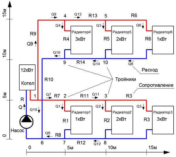
Heating system hydraulics example
And now let's look at an example of how to carry out a hydraulic calculation of a heating system. To do this, we take that section of the main line on which relatively stable heat losses are observed. It is characteristic that the diameter of the pipeline will not change.
To determine such a site, we need to be based on information about the heat balance in the building where the system itself will be located. Remember that such sections should be numbered starting from the heat generator. With regards to the nodes that will be located at the supply site, they should be signed in capital letters.
If there are no such nodes on the highway, then we only mark them with small strokes. For nodal points (they will be located in branch sections), we use Arabic numerals.If a horizontal heating system is used, then the number at each such point will indicate the floor number. The nodes for collecting the flow should also be marked with small strokes. Note that each of these numbers must necessarily consist of two digits: one for the beginning of the section, the second, therefore, for its end.
Resistance table
Important information! If a vertical type system is being calculated, then all risers should also be marked with Arabic numerals and go strictly clockwise.
Make a detailed estimate plan in advance to make it more convenient to determine the total length of the highway. The accuracy of the estimate is not just a word, the accuracy must be maintained up to ten centimeters!
Accurate heat load calculations
The value of thermal conductivity and heat transfer resistance for building materials
But still, this calculation of the optimal heat load on heating does not give the required calculation accuracy. It does not take into account the most important parameter - the characteristics of the building. The main one is the heat transfer resistance of the material for the manufacture of individual elements of the house - walls, windows, ceiling and floor. They determine the degree of conservation of thermal energy received from the heat carrier of the heating system.
What is heat transfer resistance (R)? This is the reciprocal of thermal conductivity (λ) - the ability of the material structure to transfer thermal energy. Those. the higher the thermal conductivity value, the higher the heat loss. This value cannot be used to calculate the annual heating load, since it does not take into account the thickness of the material (d). Therefore, experts use the heat transfer resistance parameter, which is calculated by the following formula:
Calculation for walls and windows
Heat transfer resistance of residential building walls
There are normalized values of the heat transfer resistance of walls, which directly depend on the region where the house is located.
In contrast to the enlarged calculation of the heating load, you first need to calculate the heat transfer resistance for external walls, windows, the floor of the first floor and the attic. Let's take as a basis the following characteristics of the house:
- Wall area - 280 m². It includes windows - 40 m²;
- The wall material is solid brick (λ=0.56). The thickness of the outer walls is 0.36 m. Based on this, we calculate the TV transmission resistance - R \u003d 0.36 / 0.56 \u003d 0.64 m² * C / W;
- To improve the thermal insulation properties, an external insulation was installed - polystyrene foam 100 mm thick. For him λ=0.036. Accordingly R \u003d 0.1 / 0.036 \u003d 2.72 m² * C / W;
- The overall R value for exterior walls is 0.64 + 2.72 = 3.36 which is a very good indicator of the thermal insulation of the house;
- Heat transfer resistance of windows - 0.75 m² * C / W (double-glazed window with argon filling).
In fact, heat losses through the walls will be:
(1/3.36)*240+(1/0.75)*40= 124 W at 1°C temperature difference
We take the temperature indicators the same as for the enlarged calculation of the heating load + 22 ° С indoors and -15 ° С outdoors. Further calculation must be done according to the following formula:
Ventilation calculation
Then you need to calculate the losses through ventilation. The total air volume in the building is 480 m³. At the same time, its density is approximately equal to 1.24 kg / m³. Those. its mass is 595 kg. On average, the air is renewed five times per day (24 hours). In this case, to calculate the maximum hourly load for heating, you need to calculate the heat losses for ventilation:
(480*40*5)/24= 4000 kJ or 1.11 kWh
Summing up all the obtained indicators, you can find the total heat loss of the house:
In this way, the exact maximum heating load is determined. The resulting value directly depends on the temperature outside. Therefore, to calculate the annual load on the heating system, it is necessary to take into account changes in weather conditions. If the average temperature during the heating season is -7°C, then the total heating load will be equal to:


(124*(22+7)+((480*(22+7)*5)/24))/3600)*24*150(heating season days)=15843 kW
By changing the temperature values, you can make an accurate calculation of the heat load for any heating system.
To the results obtained, it is necessary to add the value of heat losses through the roof and floor. This can be done with a correction factor of 1.2 - 6.07 * 1.2 \u003d 7.3 kW / h.
The resulting value indicates the actual cost of the energy carrier during the operation of the system. There are several ways to regulate the heating load of heating. The most effective of them is to reduce the temperature in rooms where there is no constant presence of residents. This can be done using temperature controllers and installed temperature sensors. But at the same time, a two-pipe heating system must be installed in the building.
To calculate the exact value of heat loss, you can use the specialized program Valtec. The video shows an example of working with it.
Anatoly Konevetsky, Crimea, Yalta
Anatoly Konevetsky, Crimea, Yalta
Dear Olga! Sorry for contacting you again.Something according to your formulas gives me an unthinkable thermal load: Cyr \u003d 0.01 * (2 * 9.8 * 21.6 * (1-0.83) + 12.25) \u003d 0.84 Qot \u003d 1.626 * 25600 * 0.37 * ((22-(-6)) * 1.84 * 0.000001 \u003d 0.793 Gcal / hour According to the enlarged formula above, it turns out only 0.149 Gcal / hour.I can’t understand what’s wrong? Please explain!
Anatoly Konevetsky, Crimea, Yalta