- Basic equations of hydraulic calculation of a gas pipeline
- Video: Fundamentals of hydraulic calculation of gas pipelines
- How to work in EXCEL
- Entering initial data
- Formulas and Algorithms
- Registration of results
- Example from Alexander Vorobyov
- Calculation of the diameter of the pipes of the heating system
- Calculation of the power of the heating system
- Coolant velocity in the system
- Calculation of the pipe diameter of the heating system
- Preparation of the calculation
- Notation and execution order
- Determination of pipe diameter
- Heat generator power
- Calculation of the thermal power of the heating system
- Thermal calculation of the house
- Thermotechnical calculation taking into account the heat losses of the house
- How to calculate the power of a gas heating boiler for the area of \u200b\u200bthe house?
- How to calculate the power of the heating boiler by the volume of the house?
- How to calculate the power of a boiler with a hot water circuit?
- What is the best way to calculate - by area or by volume?
- How much is the "extra" kilowatt?
- We also recommend seeing:
- Regarding preliminary work.
- Coolant consumption
- Hydraulic calculation of the heating system - calculation example
- Coolant consumption
- …and throughout the lifetime of the system
- Calculation of the volume of water and the capacity of the expansion tank
- Tools in the Valtec Main Menu
- Conclusions and useful video on the topic
Basic equations of hydraulic calculation of a gas pipeline
To calculate the movement of gas through pipes, the values of the pipe diameter, fuel consumption and pressure loss are taken. Calculated depending on the nature of the movement. With laminar - calculations are made strictly mathematically according to the formula:
Р1 – Р2 = ∆Р = (32*μ*ω*L)/D2 kg/m2 (20), where:
- ∆Р – kgm2, head loss due to friction;
- ω – m/s, fuel speed;
- D - m, pipeline diameter;
- L - m, pipeline length;
- μ is kg sec/m2, fluid viscosity.
With turbulent motion, it is impossible to apply accurate mathematical calculations due to the randomness of the motion. Therefore, experimentally determined coefficients are used.
Calculated according to the formula:
Р1 – Р2 = (λ*ω2*L*ρ)/2g*D (21), where:
- P1 and P2 are pressures at the beginning and end of the pipeline, kg/m2;
- λ is the dimensionless drag coefficient;
- ω – m/sec, the average speed of gas flow over the pipe section;
- ρ – kg/m3, fuel density;
- D - m, pipe diameter;
- g – m/sec2, acceleration due to gravity.
Video: Fundamentals of hydraulic calculation of gas pipelines
A selection of questions
- Mikhail, Lipetsk — What discs for metal cutting should be used?
- Ivan, Moscow — What is the GOST of metal-rolled sheet steel?
- Maksim, Tver — What are the best racks for storing rolled metal products?
- Vladimir, Novosibirsk — What does ultrasonic processing of metals mean without the use of abrasive substances?
- Valery, Moscow — How to forge a knife from a bearing with your own hands?
- Stanislav, Voronezh — What equipment is used for the production of galvanized steel air ducts?
How to work in EXCEL
The use of Excel spreadsheets is very convenient, since the results of the hydraulic calculation are always reduced to a tabular form. It is enough to determine the sequence of actions and prepare exact formulas.
Entering initial data
A cell is selected and a value is entered. All other information is simply taken into account.
| Cell | Value | Meaning, designation, unit of expression |
|---|---|---|
| D4 | 45,000 | Water consumption G in t/h |
| D5 | 95,0 | Inlet temperature tin in °C |
| D6 | 70,0 | Outlet temperature tout in °C |
| D7 | 100,0 | Inner diameter d, mm |
| D8 | 100,000 | Length, L in m |
| D9 | 1,000 | Equivalent pipe roughness ∆ in mm |
| D10 | 1,89 | The amount of odds local resistances - Σ(ξ) |
- the value in D9 is taken from the directory;
- the value in D10 characterizes the resistance at the welds.
Formulas and Algorithms
We select the cells and enter the algorithm, as well as the formulas of theoretical hydraulics.
| Cell | Algorithm | Formula | Result | Result value |
|---|---|---|---|---|
| D12 | !ERROR! D5 does not contain a number or expression | tav=(tin+tout)/2 | 82,5 | Average water temperature tav in °C |
| D13 | !ERROR! D12 does not contain a number or expression | n=0.0178/(1+0.0337*tav+0.000221*tav2) | 0,003368 | kinematic coefficient. water viscosity - n, cm2/s at tav |
| D14 | !ERROR! D12 does not contain a number or expression | ρ=(-0.003*tav2-0.1511*tav+1003, 1)/1000 | 0,970 | Average density of water ρ, t/m3 at tav |
| D15 | !ERROR! D4 does not contain a number or expression | G’=G*1000/(ρ*60) | 773,024 | Water consumption G’, l/min |
| D16 | !ERROR! D4 does not contain a number or expression | v=4*G:(ρ*π*(d:1000)2*3600) | 1,640 | Water speed v, m/s |
| D17 | !ERROR! D16 does not contain a number or expression | Re=v*d*10/n | 487001,4 | Reynolds number Re |
| D18 | !ERROR! Cell D17 does not exist | λ=64/Re at Re≤2320 λ=0.0000147*Re at 2320≤Re≤4000 λ=0.11*(68/Re+∆/d)0.25 at Re≥4000 | 0,035 | Hydraulic friction coefficient λ |
| D19 | !ERROR! Cell D18 does not exist | R=λ*v2*ρ*100/(2*9.81*d) | 0,004645 | Specific friction pressure loss R, kg/(cm2*m) |
| D20 | !ERROR! Cell D19 does not exist | dPtr=R*L | 0,464485 | Friction pressure loss dPtr, kg/cm2 |
| D21 | !ERROR! Cell D20 does not exist | dPtr=dPtr*9.81*10000 | 45565,9 | and Pa respectively D20 |
| D22 | !ERROR! D10 does not contain a number or expression | dPms=Σ(ξ)*v2*ρ/(2*9.81*10) | 0,025150 | Pressure loss in local resistances dPms in kg/cm2 |
| D23 | !ERROR! Cell D22 does not exist | dPtr \u003d dPms * 9.81 * 10000 | 2467,2 | and Pa respectively D22 |
| D24 | !ERROR! Cell D20 does not exist | dP=dPtr+dPms | 0,489634 | Estimated pressure loss dP, kg/cm2 |
| D25 | !ERROR! Cell D24 does not exist | dP=dP*9.81*10000 | 48033,1 | and Pa respectively D24 |
| D26 | !ERROR! Cell D25 does not exist | S=dP/G2 | 23,720 | Resistance characteristic S, Pa/(t/h)2 |
- the D15 value is recalculated in liters, so it is easier to perceive the flow rate;
- cell D16 - add formatting according to the condition: "If v does not fall in the range of 0.25 ... 1.5 m / s, then the background of the cell is red / the font is white."
For pipelines with a height difference between the inlet and outlet, static pressure is added to the results: 1 kg / cm2 per 10 m.
Registration of results
The author's color scheme carries a functional load:
- Light turquoise cells contain the original data - they can be changed.
- Pale green cells are input constants or data that is little subject to change.
- Yellow cells are auxiliary preliminary calculations.
- Light yellow cells are the results of calculations.
- Fonts:
- blue - initial data;
- black - intermediate/non-main results;
- red - the main and final results of the hydraulic calculation.
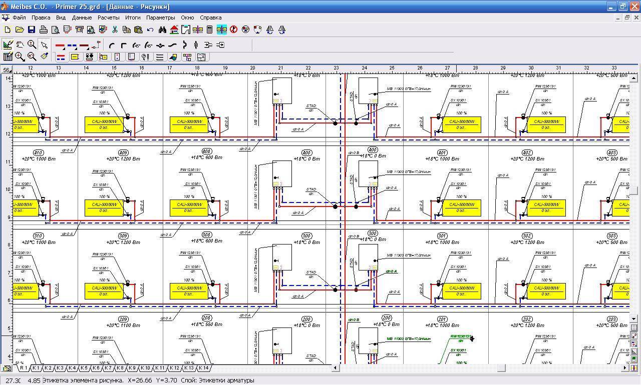
Results in Excel spreadsheet
Example from Alexander Vorobyov
An example of a simple hydraulic calculation in Excel for a horizontal pipeline section.
Initial data:
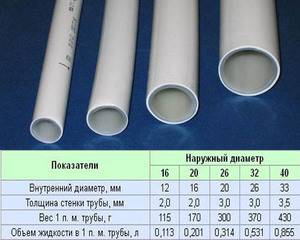
- pipe length 100 meters;
- ø108 mm;
- wall thickness 4 mm.
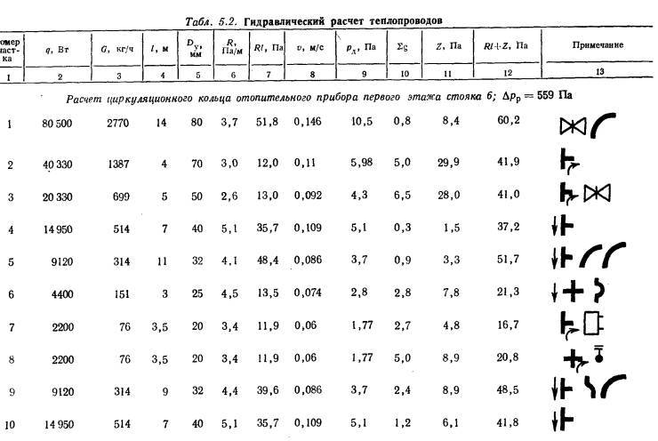
 Table of results of calculation of local resistances
Complicating step by step calculations in Excel, you better master the theory and partially save on design work. Thanks to a competent approach, your heating system will become optimal in terms of costs and heat transfer.
Calculation of the diameter of the pipes of the heating system
This calculation is based on a number of parameters. First you need to define heat output of the heating system, then calculate at what speed the coolant - hot water or another type of coolant - will move through the pipes. This will help to make calculations as accurately as possible and avoid inaccuracies.
Calculation of the power of the heating system
The calculation is made according to the formula. To calculate the power of the heating system, you need to multiply the volume of the heated room by the heat loss coefficient and the difference between the winter temperature inside and outside the room, and then divide the resulting value by 860.
If the building has standard parameters, then the calculation can be made in the average order.
To determine the resulting temperature, the average external temperature in the winter season and the internal temperature must be no less than that regulated by sanitary requirements.
Coolant velocity in the system
According to the standards, the speed of movement of the coolant through the heating pipes should exceed 0.2 meters per second. This requirement is due to the fact that at a lower speed of movement air is released from the liquid, which leads to air locks that can disrupt the operation of the entire heating system.
The upper speed level should not exceed 1.5 meters per second, as this may cause noise in the system.
In general, it is desirable to maintain a medium velocity barrier in order to increase circulation and thereby increase the productivity of the system. Most often, special pumps are used to achieve this.
Calculation of the pipe diameter of the heating system
 replacement of the entire piping system.
The pipe diameter is calculated using special formula.It includes:
- desired diameter
- thermal power of the system
- coolant speed
- the difference between the supply and return temperatures of the heating system.
This temperature difference must be chosen based on entry requirements(not less than 95 degrees) and on the return line (as a rule, it is 65-70 degrees). Based on this, the temperature difference is usually taken as 20 degrees.


Preparation of the calculation
Carrying out a qualitative and detailed calculation should be preceded by a number of preparatory measures for the implementation of the calculation schedules. This part can be called the collection of information for the calculation. Being the most difficult part in the design of a water heating system, the calculation of hydraulics allows you to accurately design all its work. The data being prepared must contain the definition of the required heat balance of the premises that will be heated by the designed heating system.
In the project, the calculation is carried out taking into account the type of selected heating devices, with certain heat exchange surfaces and their placement in heated rooms, these can be batteries of radiator sections or other types of heat exchangers. The points of their placement are indicated on the floor plans of the house or apartment.

fixing points for heating devices,
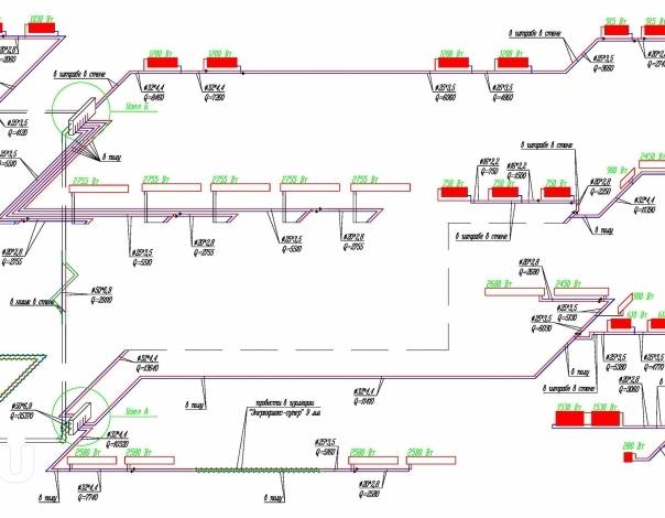
After determining the required configuration of the system on the plan, it must be drawn in axonometric projection for all floors. In such a scheme, each heater is assigned a number, the maximum thermal power is indicated. An important element, also indicated for a thermal device in the diagram, is the estimated length of the pipeline section for its connection.
Notation and execution order
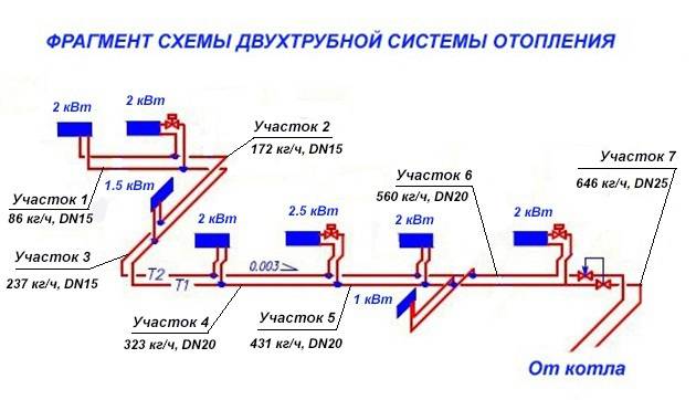
The plans must necessarily indicate a predetermined circulation ring, called the main one. It is necessarily a closed circuit, including all sections of the system pipeline with the highest coolant flow rate. For two-pipe systems, these sections go from the boiler (source of thermal energy) to the most remote thermal device and back to the boiler. For single-pipe systems, a section of the branch is taken - the riser and the back.
The unit of calculation is a pipeline section with a constant diameter and current (flow rate) of the thermal energy carrier. Its value is determined based on the heat balance of the room. A certain order of designation of such segments has been adopted, starting from the boiler (heat source, thermal energy generator), they are numbered. If there are branches from the supply line of the pipeline, their designation is done in capital letters in alphabetical order. The same letter with a stroke indicates the collection point of each branch on the return main pipeline.
In the designation of the beginning of the branch of heating devices, the number of the floor (horizontal systems) or the branch - riser (vertical) is indicated. The same number, but with a stroke, is placed at the point of their connection to the return line for collecting coolant flows. Together, these designations make up the number of each branch of the calculated section.The numbering is clockwise from the upper left corner of the plan. According to the plan, the length of each branch is also determined, the error is not more than 0.1 m.
Without going into details, it should be said that further calculations make it possible to determine the diameters of the pipes of each section of the heating system, the pressure loss on them, and to hydraulically balance all circulation rings in complex water heating systems.
Determination of pipe diameter
To finally determine the diameter and thickness of the heating pipes, it remains to discuss the issue of heat loss.

The maximum amount of heat leaves the room through the walls - up to 40%, through the windows - 15%, the floor - 10%, everything else through the ceiling / roof. The apartment is characterized by losses mainly through windows and balcony modules.
There are several types of heat loss in heated rooms:
- Flow pressure loss in a pipe. This parameter is directly proportional to the product of the specific friction loss inside the pipe (provided by the manufacturer) and the total length of the pipe. But given the current task, such losses can be ignored.
- Head loss on local pipe resistances - heat costs on fittings and inside the equipment. But given the conditions of the problem, a small number of fitting bends and the number of radiators, such losses can be neglected.
- Heat loss based on the location of the apartment. There is another type of heat cost, but it is more related to the location of the room relative to the rest of the building. For an ordinary apartment, which is located in the middle of the house and adjacent to the left / right / top / bottom with other apartments, heat losses through the side walls, ceiling and floor are almost equal to “0”.
You can only take into account the losses through the front part of the apartment - the balcony and the central window of the common room. But this question is closed by adding 2-3 sections to each of the radiators.
The value of the pipe diameter is selected according to the flow rate of the coolant and the speed of its circulation in the heating main
Analyzing the above information, it is worth noting that for the calculated speed of hot water in the heating system, the tabular speed of movement of water particles relative to the pipe wall in a horizontal position of 0.3-0.7 m / s is known.
To help the wizard, we present the so-called checklist for performing calculations for a typical hydraulic calculation of a heating system:
- data collection and calculation of boiler power;
- volume and speed of the coolant;
- heat loss and pipe diameter.
Sometimes, when calculating, it is possible to obtain a sufficiently large pipe diameter to block the calculated volume of the coolant. This problem can be solved by increasing the boiler capacity or adding an additional expansion tank.
On our website there is a block of articles devoted to the calculation of the heating system, we advise you to read:
- Thermal calculation of the heating system: how to correctly calculate the load on the system
- Calculation of water heating: formulas, rules, examples of implementation
- Thermal engineering calculation of a building: specifics and formulas for performing calculations + practical examples
Heat generator power
One of the main components of the heating system is a boiler: electric, gas, combined - at this stage it does not matter. Since its main characteristic is important to us - power, that is, the amount of energy per unit of time that will be spent on heating.
The power of the boiler itself is determined by the formula below:
Wboiler = (Sroom*Wspecific) / 10,
where:
- Sroom - the sum of the areas of all rooms that require heating;
- Wspecific - specific power, taking into account the climatic conditions of the location (that's why it was necessary to know the climate of the region).
Characteristically, for different climatic zones we have the following data:
- northern regions - 1.5 - 2 kW / m2;
- central zone - 1 - 1.5 kW / m2;
- southern regions - 0.6 - 1 kW / m2.
These figures are rather conditional, but nevertheless they give a clear numerical answer regarding the influence of the environment on the heating system of an apartment.
This map shows climatic zones with different temperature regimes. It depends on the location of housing relative to the zone how much you need to spend on heating a meter per square kilowatt of energy (+)
The amount of the area of the apartment that needs to be heated is equal to the total area of the apartment and is equal to, that is, 65.54-1.80-6.03 = 57.71 m2 (minus the balcony). The specific power of the boiler for the central region with cold winters is 1.4 kW/m2. Thus, in our example, the calculated power of the heating boiler is equivalent to 8.08 kW.
Calculation of the thermal power of the heating system
The thermal power of the heating system is the amount of heat that needs to be generated in the house for comfortable life during the cold season.
Thermal calculation of the house
There is a relationship between the total heating area and the boiler power. At the same time, the power of the boiler must be greater than or equal to the power of all heating devices (radiators). The standard heat engineering calculation for residential premises is as follows: 100 W of power per 1 m² of heated area plus 15 - 20% of the reserve.


The calculation of the number and power of heating devices (radiators) must be carried out individually for each room.Each radiator has a certain heat output. In sectional radiators, the total power is the sum of the power of all used sections.
In simple heating systems, the above methods for calculating power are sufficient. The exception is buildings with non-standard architecture, large glass areas, high ceilings and other sources of additional heat loss. In this case, a more detailed analysis and calculation using multiplying factors will be required.
Thermotechnical calculation taking into account the heat losses of the house
Calculation of heat loss at home must be performed for each room separately, taking into account windows, doors and external walls.
In more detail, the following data are used for heat loss data:
- Thickness and material of walls, coatings.
- Roof structure and material.
- Foundation type and material.
- Glazing type.
- Floor screed type.
To determine the minimum required power of the heating system, taking into account heat losses, you can use the following formula:
Qt (kWh) = V × ΔT × K ⁄ 860, where:
Qt is the heat load on the room.
V is the volume of the heated room (width × length × height), m³.
ΔT is the difference between the outdoor air temperature and the required indoor temperature, °C.
K is the heat loss coefficient of the building.
860 - conversion of the coefficient to kWh.
The heat loss coefficient of the building K depends on the type of construction and the insulation of the room:
| K | Construction type |
| 3 — 4 | A house without thermal insulation is a simplified structure or a structure made of corrugated metal sheet. |
| 2 — 2,9 | House with low thermal insulation - simplified building structure, single brickwork, simplified window and roof construction. |
| 1 — 1,9 | Medium Insulation - Standard Construction, Double Brickwork, Few Windows, Standard Roof. |
| 0,6 — 0,9 | High thermal insulation - improved construction, thermally insulated brick walls, few windows, insulated floor, high quality thermally insulated roofing pie. |
The difference between the outdoor air temperature and the required indoor temperature ΔT is determined based on the specific weather conditions and the required level of comfort in the house. For example, if the outside temperature is -20 °C, and +20 °C is planned inside, then ΔT = 40 °C.
How to calculate the power of a gas heating boiler for the area of \u200b\u200bthe house?
To do this, you will have to use the formula:
In this case, Mk is understood as the desired thermal power in kilowatts. Accordingly, S is the area of \u200b\u200byour home in square meters, and K is the specific power of the boiler - the “dose” of energy spent on heating 10 m2.
Calculation of the power of a gas boiler
How to calculate area? First of all, according to the plan of the dwelling. This parameter is indicated in the documents for the house. Don't want to search for documents? Then you will have to multiply the length and width of each room (including the kitchen, heated garage, bathroom, toilet, corridors, and so on) summing up all the obtained values.
Where can I get the value of the specific power of the boiler? Of course, in the reference literature.
If you don’t want to “dig” in directories, take into account the following values of this coefficient:
- If in your area the winter temperature does not fall below -15 degrees Celsius, the specific power factor will be 0.9-1 kW/m2.
- If in winter you observe frosts down to -25 ° C, then your coefficient is 1.2-1.5 kW / m2.
- If in winter the temperature drops to -35 ° C and lower, then in the calculations of thermal power you will have to operate with a value of 1.5-2.0 kW / m2.
As a result, the power of a boiler that heats a building of 200 "squares", located in the Moscow or Leningrad region, is 30 kW (200 x 1.5 / 10).
How to calculate the power of the heating boiler by the volume of the house?
In this case, we will have to rely on the thermal losses of the structure, calculated by the formula:
By Q in this case we mean the calculated heat loss. In turn, V is the volume, and ∆T is the temperature difference between inside and outside the building. Under k is understood the coefficient of thermal dissipation, which depends on the inertia of building materials, door leaf and window sashes.
We calculate the volume of the cottage
How to determine the volume? Of course, according to the building plan. Or by simply multiplying the area by the height of the ceilings. The temperature difference is understood as the "gap" between the generally accepted "room" value - 22-24 ° C - and the average readings of a thermometer in winter.


The coefficient of thermal dissipation depends on the heat resistance of the structure.
Therefore, depending on the building materials and technologies used, this coefficient takes the following values:
- From 3.0 to 4.0 - for frameless warehouses or frame storages without wall and roof insulation.
- From 2.0 to 2.9 - for technical buildings made of concrete and brick, supplemented with minimal thermal insulation.
- From 1.0 to 1.9 - for old houses built before the era of energy-saving technologies.
- From 0.5 to 0.9 - for modern houses built in accordance with modern energy-saving standards.
As a result, the power of the boiler heating a modern, energy-saving building with an area of 200 square meters and a 3-meter ceiling, located in a climatic zone with 25-degree frosts, reaches 29.5 kW (200x3x (22 + 25) x0.9 / 860).
How to calculate the power of a boiler with a hot water circuit?
Why do you need a 25% headroom? First of all, to replenish energy costs due to the "outflow" of heat to the hot water heat exchanger during the operation of two circuits. Simply put: so that you do not freeze after taking a shower.
Solid fuel boiler Spark KOTV - 18V with a hot water circuit
As a result, a double-circuit boiler serving the heating and hot water systems in a house of 200 "squares", which is located north of Moscow, south of St. Petersburg, should generate at least 37.5 kW of thermal power (30 x 125%).
What is the best way to calculate - by area or by volume?
In this case, we can only give the following advice:
- If you have a standard layout with a ceiling height of up to 3 meters, then count by area.
- If the ceiling height exceeds the 3-meter mark, or if the building area is more than 200 square meters - count by volume.
How much is the "extra" kilowatt?
Taking into account the 90% efficiency of an ordinary boiler, for the production of 1 kW of thermal power, it is necessary to consume at least 0.09 cubic meters of natural gas with a calorific value of 35,000 kJ/m3. Or about 0.075 cubic meters of fuel with a maximum calorific value of 43,000 kJ/m3.
As a result, during the heating period, an error in calculations per 1 kW will cost the owner 688-905 rubles.Therefore, be careful in your calculations, buy boilers with adjustable power and do not strive to "bloat" the heat generating capacity of your heater.
We also recommend seeing:
- LPG gas boilers
- Double-circuit solid fuel boilers for long burning
- Steam heating in a private house
- Chimney for solid fuel heating boiler
Regarding preliminary work.
Due to the fact that the hydraulic calculation requires a lot of time and effort, we need to first perform some calculations:
- Determine the balance of rooms and rooms that are heated.
- Decide on the type of heating equipment and heat exchanger. Arrange them according to the general plan of the building.
- Before proceeding with the calculation, it is necessary to select pipelines and decide on the configuration of the heating system as a whole.
- It is necessary to make a drawing of the system, preferably an axonometric diagram. In it, indicate the length of the sections, the numbers and the magnitude of the load.
- The circulation ring should also be installed in advance.
Important! If the calculation concerns a wooden house, then there will be no differences between it and brick, concrete, etc.
will not.
Coolant consumption
The coolant flow rate is calculated by the formula:
,
where Q is the total power of the heating system, kW; taken from the calculation of the heat loss of the building
Cp is the specific heat capacity of water, kJ/(kg*deg.C); for simplified calculations, we take equal to 4.19 kJ / (kg * deg. C)
ΔPt is the temperature difference at the inlet and outlet; usually we take the supply and return of the boiler
Heat carrier flow calculator (only for water)
Q = kW; Δt = oC; m = l/s
In the same way, you can calculate the flow rate of the coolant in any section of the pipe.The sections are selected so that the pipe has the same water velocity. Thus, partitioning into sections occurs before the tee, or before reduction. It is necessary to sum by power all the radiators to which the coolant flows through each section of the pipe. Then substitute the value into the formula above. These calculations must be made for the pipes in front of each radiator.
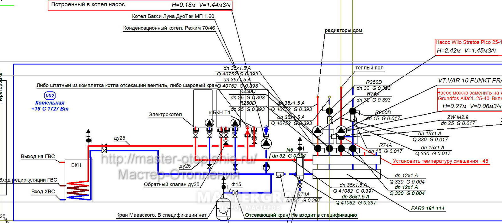
Hydraulic calculation of the heating system - calculation example
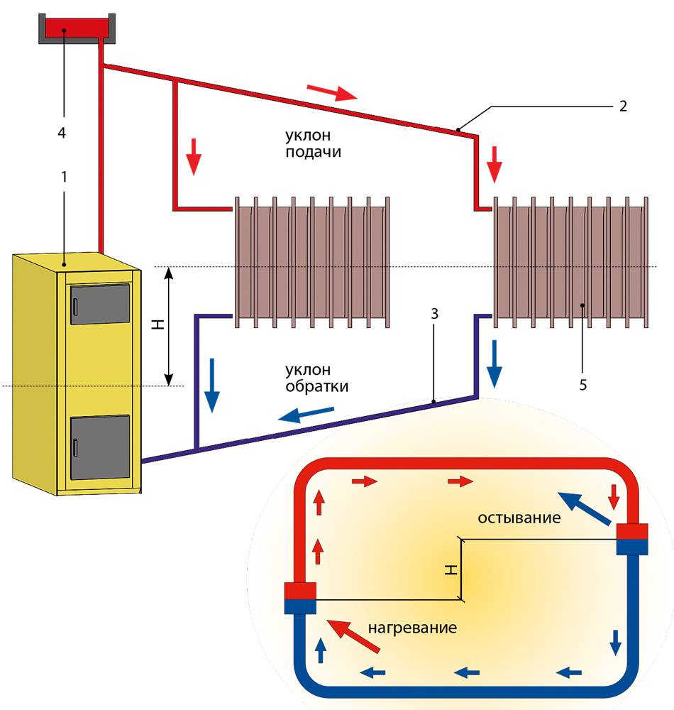
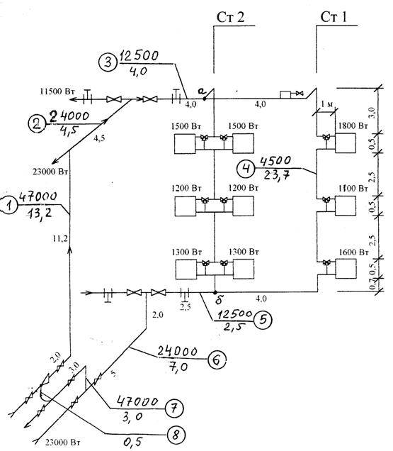
As an example, consider a two-pipe gravity heating system.
Initial data for calculation:
- calculated thermal load of the system - Qsp. = 133 kW;
- system parameters - tg = 750С, tо = 600С;
- coolant flow rate (calculated) – Vco = 7.6 m3/h;
- the heating system is connected to the boilers through a hydraulic separator of a horizontal type;
- the automation of each of the boilers throughout the year maintains a constant temperature of the coolant at the outlet - tg = 800C;
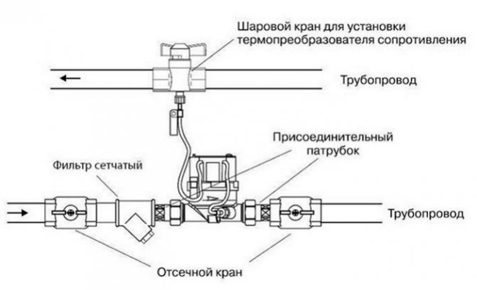
- an automatic differential pressure regulator is installed at the inlet of each distributor;
- the heating system from the distributors is assembled from metal-plastic pipes, and the heat supply to the distributors is carried out by means of steel pipes (water and gas pipes).
The diameters of the pipeline sections were selected using a nomogram for a given coolant velocity of 0.4-0.5 m/s.
In section 1, a DN 65 valve is installed. Its resistance, according to the manufacturer's information, is 800 Pa.
In section 1a, a filter with a diameter of 65 mm and a throughput of 55 m3/h is installed. The resistance of this element will be:
0.1 x (G / kv) x 2 \u003d 0.1 x (7581/55) x 2 \u003d 1900 Pa.
The resistance of the three-way valve dу = 40 mm and kv = 25 m3/h will be 9200 Pa.
Similarly, the calculation of the remaining parts of the heat supply system of the distributors is carried out. When calculating the heating system, the main circulation ring is selected from the distributor through the most loaded heating device. Hydraulic calculation is made using the 1st direction.
Coolant consumption
Coolant consumption
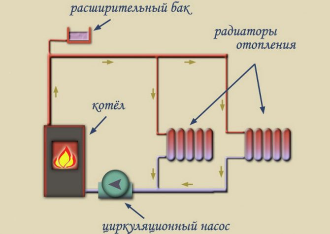
To show how the hydraulic calculation of heating is carried out, let's take for example a simple heating scheme, which includes a heating boiler and heating radiators with a kilowatt heat consumption. And there are 10 such radiators in the system.


Here it is important to correctly divide the entire scheme into sections, and at the same time strictly adhere to one rule - in each section, the diameter of the pipes should not change. So, the first section is a pipeline from the boiler to the first heater. The second section is a pipeline between the first and second radiator
And so on
The second section is a pipeline between the first and second radiator. And so on
So, the first section is a pipeline from the boiler to the first heater. The second section is a pipeline between the first and second radiator. And so on.
How does heat transfer occur, and how does the temperature of the coolant decrease? Getting into the first radiator, the coolant gives off part of the heat, which is reduced by 1 kilowatt. It is in the first section that the hydraulic calculation is made under 10 kilowatts. But in the second section it is already under 9. And so on with a decrease.
There is a formula by which you can calculate the flow rate of the coolant:
G \u003d (3.6 x Qch) / (with x (tr-to))
Qch is the calculated heat load of the site. In our example, for the first section it is 10 kW, for the second 9.
c is the specific heat capacity of water, the indicator is constant and equal to 4.2 kJ / kg x C;
tr is the temperature of the coolant at the entrance to the section;
to is the temperature of the coolant at the exit from the site.
…and throughout the lifetime of the system
We want the hydraulic system to perform as it should, throughout its life. With TA SCOPE and TA Select, you can easily check if the system is working properly.
In TA SCOPE flow, differential pressure, 2 temperatures, differential temperature and power are entered. To analyze these measured data, they are loaded into TA Select.
After baseline data collection, determining the heat losses of the house and the power of the radiators, it remains to perform a hydraulic calculation of the heating system. Correctly executed, it is a guarantee of correct, silent, stable and reliable operation of the heating system. Moreover, it is a way to avoid unnecessary capital investments and energy costs.
Calculation of the volume of water and the capacity of the expansion tank

To calculate the performance of the expansion tank, which is mandatory for any closed-type heating system, you will need to understand the phenomenon of increasing the volume of liquid in it. This indicator is estimated taking into account changes in the main performance characteristics, including fluctuations in its temperature. In this case, it varies in a very wide range - from room temperature +20 degrees and up to operating values within 50-80 degrees.
It will be possible to calculate the volume of the expansion tank without unnecessary problems, if you use a rough estimate that has been proven in practice.It is based on the experience of operating the equipment, according to which the volume of the expansion tank is approximately one tenth of the total amount of coolant circulating in the system.
At the same time, all its elements are taken into account, including heating radiators (batteries), as well as the water jacket of the boiler unit. To determine the exact value of the desired indicator, you will need to take the passport of the equipment in use and find in it the items relating to the capacity of the batteries and the working tank of the boiler. After their determination, it is not difficult to find the excess coolant in the system
To do this, the cross-sectional area of polypropylene pipes is first calculated, and then the resulting value is multiplied by the length of the pipeline. After summing up for all branches of the heating system, the numbers taken from the passport for radiators and the boiler are added to them. One tenth of the total is then deducted
After their determination, it is not difficult to find the excess coolant in the system. To do this, the cross-sectional area of polypropylene pipes is first calculated, and then the resulting value is multiplied by the length of the pipeline. After summing up for all branches of the heating system, the numbers taken from the passport for radiators and the boiler are added to them. One tenth of the total is then counted.
Tools in the Valtec Main Menu
Valtec, like any other program, has a main menu at the top.
We click on the "File" button and in the submenu that opens we see the standard tools known to any computer user from other programs:
The "Calculator" program, built into Windows, is launched - to perform calculations:
With the help of the "Converter" we will convert one unit of measure to another:
There are three columns here:
In the far left, we select the physical quantity with which we are working, for example, pressure. In the middle column - the unit from which you want to convert (for example, Pascals - Pa), and in the right - to which you want to convert (for example, into technical atmospheres). There are two lines in the upper left corner of the calculator, we will drive the value obtained during the calculations into the upper one, and the conversion to the required units of measurement will be immediately displayed in the lower one ... But we will talk about all this in due time, when it comes to practice.


In the meantime, we continue to get acquainted with the "Tools" menu. Form Generator:
This is necessary for designers who carry out projects to order. If we do heating only in our house, then we don’t need the Form Generator.
The next button in the main menu of the Valtec program is "Styles":
It is to control the appearance of the program window - it adjusts to the software that is installed on your computer. For me, this is such an unnecessary gadget, because I am one of those for whom the main thing is not “checkers”, but to get there. And you decide for yourself.
Let's take a closer look at the tools under this button.
In "Climatology" we select the construction area:
Heat loss in the house depends not only on the materials of the walls and other structures, but also on the climate of the area where the building is located. Consequently, the requirements for the heating system depend on the climate.
In the left column we find the area in which we live (republic, region, region, city). If our settlement is not here, then choose the nearest one.
"Materials". Here are the parameters of various building materials used in the construction of houses.That is why, when collecting initial data (see previous design materials), we listed the materials of walls, floors, ceilings:
Hole tool. Here is the information on door and window openings:
"Pipes". Here is collected information about the parameters of pipes used in heating systems: internal and external dimensions, resistance coefficients, roughness of internal surfaces:
We will need this in hydraulic calculations - to determine the power of the circulation pump.
"Heaters". Actually, there is nothing here except the characteristics of those coolants that can be poured into the heating system of the house:
These characteristics are heat capacity, density, viscosity.
Water is not always used as a coolant, it happens that antifreezes are poured into the system, which are called “non-freezing” in the common people. We will talk about the choice of coolant in a separate article.
"Consumers" for calculating the heating system are not needed, because this tool for calculating water supply systems:
"KMS" (coefficients of local resistance):
Any heating device (radiator, valve, thermostat, etc.) creates resistance to the movement of the coolant, and these resistances must be taken into account in order to correctly select the power of the circulation pump.
"Devices according to DIN". This, like "Consumers", is more about water supply systems:
Conclusions and useful video on the topic
Features, advantages and disadvantages of natural and forced coolant circulation systems for heating systems:
Summing up the calculations of the hydraulic calculation, as a result, we received specific physical characteristics of the future heating system.
Naturally, this is a simplified calculation scheme that gives approximate data regarding the hydraulic calculation for the heating system of a typical two-room apartment.
Are you trying to independently carry out a hydraulic calculation of the heating system? Or maybe you do not agree with the material presented? We are waiting for your comments and questions - the feedback block is located below.