- Code of Practice for Design and Construction general provisions for the design and construction of gas distribution systems from metal and polyethylene pipes the general provision and construction gas distribution system from steel and
- Hydraulic calculation of a gas pipeline: methods and methods of calculation + calculation example
- Why is it necessary to calculate the gas pipeline
- Determination of the number of gas control points of hydraulic fracturing
- Program overview
- Theory of hydraulic calculation of the heating system.
- Determination of pressure losses in pipes
- 1.4 Distribution of pressure in sections of the pipeline system
- PC calculation option
- Program overview
- .1 Determining the capacity of a complex gas pipeline
- Program overview
- Determination of pressure losses in pipes
- hydraulic balancing
- Results.
Code of Practice for Design and Construction general provisions for the design and construction of gas distribution systems from metal and polyethylene pipes the general provision and construction gas distribution system from steel and
CALCULATION OF GAS PIPELINE DIAMETER AND PERMISSIBLE PRESSURE LOSS
3.21 The throughput capacity of gas pipelines can be taken from the conditions for creating, at the maximum allowable gas pressure loss, the most economical and reliable system in operation, which ensures the stability of the operation of hydraulic fracturing and gas control units (GRU), as well as the operation of consumer burners in acceptable gas pressure ranges.
3.22 The calculated internal diameters of gas pipelines are determined based on the condition of ensuring uninterrupted gas supply to all consumers during the hours of maximum gas consumption.
3.23 The calculation of the diameter of the gas pipeline should be performed, as a rule, on a computer with the optimal distribution of the calculated pressure loss between the sections of the network.
If it is impossible or inappropriate to perform the calculation on a computer (lack of an appropriate program, separate sections of gas pipelines, etc.), it is allowed to perform a hydraulic calculation according to the formulas below or according to nomograms (Appendix B) compiled according to these formulas.
3.24 Estimated pressure losses in high and medium pressure gas pipelines are accepted within the pressure category adopted for the gas pipeline.
3.25 Estimated total gas pressure losses in low-pressure gas pipelines (from the gas supply source to the most remote device) are assumed to be no more than 180 daPa, including 120 daPa in distribution gas pipelines, 60 daPa in inlet gas pipelines and internal gas pipelines.
3.26 The values of the calculated pressure loss of gas when designing gas pipelines of all pressures for industrial, agricultural and household enterprises and public utilities are accepted depending on the gas pressure at the connection point, taking into account the technical characteristics of the gas equipment accepted for installation, safety automation devices and process control automation mode of thermal units.
3.27 The pressure drop in the gas network section can be determined:
- for networks of medium and high pressure according to the formula
- for low pressure networks according to the formula
– for a hydraulically smooth wall (inequality (6) is valid):
– at 4000 100000
3.29 Estimated gas consumption in sections of low-pressure distribution external gas pipelines with gas travel costs should be determined as the sum of transit and 0.5 gas travel costs in this section.
3.30 The pressure drop in local resistances (elbows, tees, stop valves, etc.) can be taken into account by increasing the actual length of the gas pipeline by 5-10%.
3.31 For external above-ground and internal gas pipelines, the estimated length of gas pipelines is determined by the formula (12)
3.32 In cases where LPG gas supply is temporary (with subsequent transfer to natural gas supply), gas pipelines are designed with the possibility of their future use on natural gas.
In this case, the amount of gas is determined as equivalent (in terms of calorific value) to the estimated consumption of LPG.
3.33 The pressure drop in the pipelines of the liquid phase of LPG is determined by the formula (13)
Taking into account the anti-cavitation reserve, the average velocities of the liquid phase are accepted: in the suction pipelines - no more than 1.2 m/s; in pressure pipelines - no more than 3 m / s.
3.34 Calculation of the diameter of the LPG vapor phase gas pipeline is carried out in accordance with the instructions for the calculation of natural gas pipelines of the corresponding pressure.
3.35 When calculating internal low-pressure gas pipelines for residential buildings, it is allowed to determine the gas pressure loss due to local resistances in the amount,%:
- on gas pipelines from inputs to the building:
- on the intra-apartment wiring:
3.37 Calculation of ring networks of gas pipelines should be carried out with the linkage of gas pressures at the nodal points of the design rings. The problem of pressure loss in the ring is allowed up to 10%.
3.38 When performing hydraulic calculation of above-ground and internal gas pipelines, taking into account the degree of noise generated by gas movement, it is necessary to take gas movement speeds of no more than 7 m/s for low-pressure gas pipelines, 15 m/s for medium-pressure gas pipelines, 25 m/s for high-pressure gas pipelines pressure.
3.39 When performing hydraulic calculation of gas pipelines, carried out according to formulas (5) - (14), as well as using various methods and programs for electronic computers, compiled on the basis of these formulas, the estimated inner diameter of the gas pipeline should be preliminarily determined by formula (15)
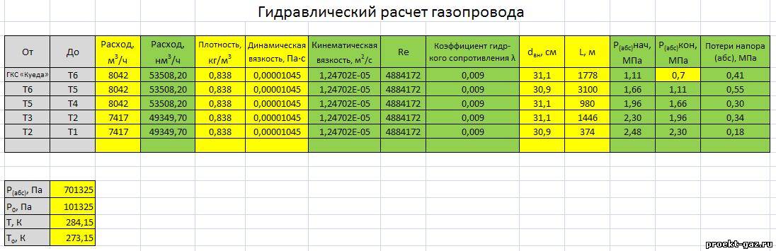
Hydraulic calculation of a gas pipeline: methods and methods of calculation + calculation example
For safe and trouble-free operation of gas supply, it must be designed and calculated
It is important to perfectly select pipes for lines of all types of pressure, ensuring a stable supply of gas to the devices
In order for the selection of pipes, fittings and equipment to be as accurate as possible, a hydraulic calculation of the pipeline is carried out. How to make it? Admit it, you are not too knowledgeable in this matter, let's figure it out.
We offer you to get acquainted with scrupulously selected and thoroughly processed information about production options. hydraulic calculation for gas pipeline systems. Using the data presented by us will ensure the supply of blue fuel with the required pressure parameters to the devices. Carefully verified data is based on the regulation of regulatory documentation.
The article describes in detail the principles and schemes of computations. An example of performing calculations is given. Graphical applications and video instructions are used as a useful informative addition.
Why is it necessary to calculate the gas pipeline
Calculations are carried out throughout all sections of the gas pipeline to identify places where possible resistances are likely to appear in the pipes, changing the fuel supply rate.
If all calculations are done correctly, then the most suitable equipment can be selected and an economical and efficient design of the entire structure of the gas system can be created.
This will save you from unnecessary, overestimated indicators during operation and costs in construction, which could be during the planning and installation of the system without hydraulic calculation of the gas pipeline.
There is a better opportunity to select the required sectional size and pipe materials for more efficient, fast and stable supply of blue fuel to the planned points of the gas pipeline system.
The optimal operating mode of the entire gas pipeline is ensured.
Developers receive financial benefits from savings on the purchase of technical equipment and building materials.
The correct calculation of the gas pipeline is made, taking into account the maximum levels of fuel consumption during periods of mass consumption. All industrial, municipal, individual household needs are taken into account.
Determination of the number of gas control points of hydraulic fracturing
Gas control points are designed to reduce gas pressure and maintain it at a given level, regardless of the flow rate.
With a known estimated consumption of gaseous fuel, the city district determines the number of hydraulic fracturing, based on the optimal hydraulic fracturing performance (V=1500-2000 m3/hour) according to the formula:
n = , (27)
where n is the number of hydraulic fracturing, pcs.;
VR — estimated gas consumption by the city district, m3/hour;
Vwholesale — optimum productivity of hydraulic fracturing, m3/hour;
n=586.751/1950=3.008 pcs.
After determining the number of hydraulic fracturing stations, their location is planned on the general plan of the city district, installing them in the center of the gasified area on the territory of the quarters.
Program overview
For the convenience of calculations, amateur and professional programs for calculating hydraulics are used.
The most popular is Excel.
You can use the online calculation in Excel Online, CombiMix 1.0, or the online hydraulic calculator. The stationary program is selected taking into account the requirements of the project.
The main difficulty in working with such programs is ignorance of the basics of hydraulics. In some of them, there is no decoding of formulas, the features of branching of pipelines and the calculation of resistances in complex circuits are not considered.
- HERZ C.O. 3.5 - makes a calculation according to the method of specific linear pressure losses.
- DanfossCO and OvertopCO can count natural circulation systems.
- "Flow" (Flow) - allows you to apply the calculation method with a variable (sliding) temperature difference along the risers.
You should specify the data entry parameters for temperature - Kelvin / Celsius.
Theory of hydraulic calculation of the heating system.
Theoretically, the heating GR is based on the following equation:
∆P = R·l + z
This equality is valid for a specific area. This equation is deciphered as follows:
- ΔP - linear pressure loss.
- R is the specific pressure loss in the pipe.
- l is the length of the pipes.
- z - pressure losses in the outlets, shutoff valves.
It can be seen from the formula that the greater the pressure loss, the longer it is and the more bends or other elements in it that reduce the passage or change the direction of the fluid flow. Let's deduce what R and z are equal to. To do this, consider another equation showing the pressure loss due to friction against the pipe walls:
friction
This is the Darcy-Weisbach equation. Let's decode it:
- λ is a coefficient depending on the nature of the movement of the pipe.
- d is the inner diameter of the pipe.
- v is the velocity of the fluid.
- ρ is the density of the liquid.
From this equation, an important relationship is established - the pressure loss due to friction is the smaller, the larger the inner diameter of the pipes and the lower the fluid velocity. Moreover, the dependence on speed is quadratic here. Losses in bends, tees and valves are determined by a different formula:


∆Pfittings = ξ*(v²ρ/2)
Here:
- ξ is the coefficient of local resistance (hereinafter referred to as CMR).
- v is the velocity of the fluid.
- ρ is the density of the liquid.
It can also be seen from this equation that the pressure drop increases with increasing fluid velocity.Also, it is worth saying that in the case of using a low-freezing coolant, its density will also play an important role - the higher it is, the harder it is for the circulation pump. Therefore, when switching to “anti-freeze”, it may be necessary to replace the circulation pump.
From the above, we derive the following equality:
∆P=∆Pfriction +∆Pfittings=((λ/d)(v²ρ/2)) + (ξ(v²ρ/2)) = ((λ/α)l(v²ρ/2)) + (ξ*(v²ρ/2)) = R•l +z;
From this we obtain the following equalities for R and z:
R = (λ/α)*(v²ρ/2) Pa/m;
z = ξ*(v²ρ/2) Pa;
Now let's figure out how to calculate the hydraulic resistance using these formulas.
Determination of pressure losses in pipes
The pressure loss resistance in the circuit through which the coolant circulates is determined as their total value for all individual components. The latter include:
- losses in the primary circuit, denoted as ∆Plk;
- local heat carrier costs (∆Plm);
- pressure drop in special zones, called “heat generators” under the designation ∆Ptg;
- losses inside the built-in heat exchange system ∆Pto.
After summing these values, the desired indicator is obtained, which characterizes the total hydraulic resistance of the system ∆Pco.
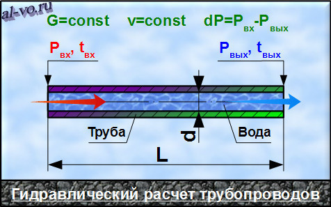
In addition to this generalized method, there are other ways to determine the head loss in polypropylene pipes. One of them is based on a comparison of two indicators tied to the beginning and end of the pipeline. In this case, the pressure loss can be calculated by simply subtracting its initial and final values, determined by two pressure gauges.
Another option for calculating the desired indicator is based on the use of a more complex formula that takes into account all the factors that affect the characteristics of the heat flux.The ratio given below primarily takes into account the loss of liquid head due to the long length of the pipeline.
- h is the liquid head loss, measured in meters in the case under study.
- λ is the coefficient of hydraulic resistance (or friction), determined by other calculation methods.
- L is the total length of the serviced pipeline, which is measured in running meters.
- D is the internal size of the pipe, which determines the volume of the coolant flow.
- V is the fluid flow rate, measured in standard units (meter per second).
- The symbol g is the free fall acceleration, which is 9.81 m/s2.
Of great interest are the losses caused by the high coefficient of hydraulic friction. It depends on the roughness of the inner surfaces of the pipes. The ratios used in this case are valid only for tubular blanks of a standard round shape. The final formula for finding them looks like this:
- V - the speed of movement of water masses, measured in meters / second.
- D - inner diameter, which determines the free space for the movement of the coolant.
- The coefficient in the denominator indicates the kinematic viscosity of the liquid.
The latter indicator refers to constant values and is found according to special tables published in large quantities on the Internet.
1.4 Distribution of pressure in sections of the pipeline system
Calculate the pressure at the nodal point p1 and build a pressure graph
Location on l1 by formula (1.1):
(1.31)

(1.32)
Imagine
resulting dependence pl1=f(l) in the form of a table.
Table
4
| l,km | 5 | 10 | 15 | 20 | 25 | 30 | 34 |
| p,kPa | 4808,3 | 4714,8 | 4619,5 | 4522,1 | 4422,6 | 4320,7 | 4237,5 |
Calculate the pressure at the nodal point p6 and build a pressure graph
on the branches l8 — l9 by formula (1.13):
 (1.33)
(1.34)

Imagine
resulting dependence p(l8-l9)=f(l) in the form of a table.
Table
5
| l,km | 87 | 90,38 | 93,77 | 97,15 | 100,54 | 104 | 107,31 |
| p,kPa | 2963,2 | 2929,9 | 2897,2 | 2864,1 | 2830,7 | 2796,8 | 2711 |
| l,km | 110,69 | 114,08 | 117,46 | 120,85 | 124,23 | 127,62 | 131 |
| p,kPa | 2621,2 | 2528,3 | 2431,8 | 2331,4 | 2226,4 | 2116,2 | 2000 |
To calculate costs per branch l2 —l4 —l6 andl3 —l5 —l7, we use formulas (1.10) and
(1.11):


We check:
Calculation
done correctly.
Now
calculate the pressure at the nodal points of the branch l2 —l4
—l6 on
formulas (1.2), (1.3) and (1.4) :


results
section pressure calculation l2
presented in table 6:
Table
6
| l,km | 34 | 38,5 | 43 | 47,5 | 52 | 56,5 | 61 |
| p,kPa | 4240 | 4123,8 | 4004,3 | 3881,1 | 3753,8 | 3622,1 | 3485,4 |


results
section pressure calculation l4
are presented in table 7:
Table
7
PC calculation option
Performing the calculus using a computer is the least laborious - all that is required of a person is to insert the necessary data into the appropriate columns.
Therefore, a hydraulic calculation is done in a few minutes, and this operation does not require a large stock of knowledge, which is necessary when using formulas.
For its correct implementation, it is necessary to take the following data from the technical specifications:
- gas density;
- coefficient of kinetic viscosity;
- gas temperature in your region.
The necessary technical conditions are obtained from the city gas department of the settlement where the gas pipeline will be built. Actually, the design of any pipeline begins with the receipt of this document, because it contains all the basic requirements for its design.
Next, the developer needs to find out the gas consumption for each device that is planned to be connected to the gas pipeline. For example, if the fuel will be transported to a private house, then stoves for cooking, all kinds of heating boilers are most often used there, and the necessary numbers are always in their passports.
In addition, you will need to know the number of burners for each stove that will be connected to the pipe.
At the next stage of collecting the necessary data, information about the pressure drop at the installation sites of any equipment is selected - this can be a meter, a shut-off valve, a thermal shut-off valve, a filter, and other elements.
In this case, it is easy to find the necessary numbers - they are contained in a special table attached to the passport of each product.
The designer should pay attention to the fact that the pressure drop at maximum gas consumption should be indicated.
At the next stage, it is recommended to find out what the blue fuel pressure will be at the tie-in point. Such information may contain the technical specifications of your Gorgaz, a previously drawn up scheme of the future gas pipeline.
If the network will consist of several sections, then they must be numbered and indicate the actual length. In addition, for each, all variable indicators should be prescribed separately - this is the total flow rate of any device that will be used, the pressure drop, and other values.
A simultaneity factor is required. It takes into account the possibility of joint operation of all gas consumers connected to the network. For example, all heating equipment located in an apartment building or a private house.
Such data is used by the hydraulic calculation program to determine the maximum load in any section or in the entire gas pipeline.
For each individual apartment or house, the specified coefficient does not need to be calculated, since its values are known and are indicated in the table below:
If at some facility it is planned to use more than two heating boilers, furnaces, storage water heaters, then the simultaneity indicator will always be 0.85.Which will need to be indicated in the corresponding column used for the calculation of the program.
Next, you should specify the diameter of the pipes, and you will also need their roughness coefficients, which will be used in the construction of the pipeline. These values are standard and can be easily found in the Rulebook.
Program overview
For the convenience of calculations, amateur and professional programs for calculating hydraulics are used.
The most popular is Excel.
You can use the online calculation in Excel Online, CombiMix 1.0, or the online hydraulic calculator. The stationary program is selected taking into account the requirements of the project.
The main difficulty in working with such programs is ignorance of the basics of hydraulics. In some of them, there is no decoding of formulas, the features of branching of pipelines and the calculation of resistances in complex circuits are not considered.
Program features:
- HERZ C.O. 3.5 - makes a calculation according to the method of specific linear pressure losses.
- DanfossCO and OvertopCO can count natural circulation systems.
- "Flow" (Flow) - allows you to apply the calculation method with a variable (sliding) temperature difference along the risers.
You should specify the data entry parameters for temperature - Kelvin / Celsius.
.1 Determining the capacity of a complex gas pipeline
To calculate a complex pipeline system according to Figure 1 and data
Table 1, we will use the replacement method for an equivalent simple gas pipeline. For
this, based on the theoretical flow equation for steady state
isothermal flow, we compose an equation for an equivalent gas pipeline and
let's write the equation.
Table 1
| Index number i | Outside diameter Di , mm | Wall thickness δi , mm | Section length Li , km |
| 1 | 508 | 9,52 | 34 |
| 2 | 377 | 7 | 27 |
| 3 | 426 | 9 | 17 |
| 4 | 426 | 9 | 12 |
| 5 | 377 | 7 | 8 |
| 6 | 377 | 7 | 9 |
| 7 | 377 | 7 | 28 |
| 8 | 630 | 10 | 17 |
| 9 | 529 | 9 | 27 |
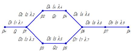
Figure 1 - Diagram of the pipeline
For plot l1 write down
expense formula:
(1.1)
At the nodal point p1 the gas flow is divided into two threads: l2 —l4 —l6 andl3 —l5 —l7 further at the point p6 these branches
unite. We consider that in the first branch the flow rate is Q1, and in the second branch Q2.


For branch l2 —l4 —l6:
(1.2)
(1.3)
(1.4)
Let's sum up
pairwise (1.2), (1.3) and (1.4), we get:
(1.5)
For
branches l3 —l5 —l7:
(1.6)
(1.7)
(1.8)
Let's sum up
pairwise (1.6), (1.7) and (1.8), we get:
(1.9)
Express
from expressions (1.5) and (1.9) Q1 and Q2, respectively:
(1.10)
(1.11)
Consumption
along the parallel section is equal to: Q=Q1+Q2.
 (1.12)
Difference
squares of pressure for a parallel section is equal to:
 (1.13)
For
branches l8-l9 we write:
(1.14)
Summing up (1.1), (1.13) and (1.14), we get:
 (1.15)
From
The last expression can determine the throughput of the system. Taking into account
flow formulas for an equivalent gas pipeline:
(1.16)
Let us find a relation that allows, for a given LEK or DEK, to find another geometric size of the gas pipeline
 (1.17)
In order to determine the length of the equivalent gas pipeline, we construct
system deployment. To do this, we will build all the threads of a complex pipeline in one
direction while maintaining the structure of the system. As a length equivalent
pipeline, we will take the longest component of the gas pipeline from its beginning to
end as shown in Figure 2.
Figure 2 - Development of the pipeline system
According to the results of construction as the length of the equivalent pipeline
take the length equal to the sum of the sections l1 —l3 —l5 —l7 —l8 —l9. Then LEK=131km.
For calculations, we will take the following assumptions: we consider that the gas flow in
pipeline obeys the quadratic law of resistance. That's why
the coefficient of hydraulic resistance is calculated by the formula:
, (1.18)
where k is the equivalent wall roughness
pipes, mm;
D-
internal diameter of a pipe, mm.
For main gas pipelines without backing rings, additional
local resistances (fittings, transitions) usually do not exceed 2-5% of losses
for friction. Therefore, for technical calculations for the design coefficient
hydraulic resistance value is taken:
(1.19)
For
further calculation we accept , k=0,5.
Calculate
coefficient of hydraulic resistance for all sections of the pipeline
networks, the results are entered in table 2.
Table
2
| Index number i | Outside diameter Di , mm | Wall thickness δi , mm | Hydraulic resistance coefficient, |
| 1 | 508 | 9,52 | 0,019419 |
| 2 | 377 | 7 | 0,020611 |
| 3 | 426 | 9 | 0,020135 |
| 4 | 426 | 9 | 0,020135 |
| 5 | 377 | 7 | 0,020611 |
| 6 | 377 | 7 | 0,020611 |
| 7 | 377 | 7 | 0,020611 |
| 8 | 630 | 10 | 0,018578 |
| 9 | 529 | 9 | 0,019248 |
In calculations, we use the average gas density in the pipeline system,
which we calculate from the conditions of gas compressibility at medium pressure.
The average pressure in the system under given conditions is:
(1.20)
To determine the compressibility coefficient according to the nomogram, it is necessary
calculate the reduced temperature and pressure using the formulas:
, (1.21)
, (1.22)
where T, p — temperature and pressure under operating conditions;
Tkr, rkr are the absolute critical temperature and pressure.
According to appendix B: Tkr\u003d 190.9 K, rkr =4.649 MPa.
Further
according to the nomogram for calculating the compressibility factor of natural gas, we determine z =
0,88.
middle
the gas density is determined by the formula:
(1.23)
For
calculation of the flow through the gas pipeline, it is necessary to determine the parameter A:
(1.24)
Let's find
:
Let's find
gas flow through the system:
(1.25)
(1.26)

Program overview
For the convenience of calculations, amateur and professional programs for calculating hydraulics are used.
The most popular is Excel.
You can use the online calculation in Excel Online, CombiMix 1.0, or the online hydraulic calculator. The stationary program is selected taking into account the requirements of the project.


The main difficulty in working with such programs is ignorance of the basics of hydraulics. In some of them, there is no decoding of formulas, the features of branching of pipelines and the calculation of resistances in complex circuits are not considered.
- HERZ C.O. 3.5 - makes a calculation according to the method of specific linear pressure losses.
- DanfossCO and OvertopCO can count natural circulation systems.
- "Flow" (Flow) - allows you to apply the calculation method with a variable (sliding) temperature difference along the risers.
You should specify the data entry parameters for temperature - Kelvin / Celsius.
Determination of pressure losses in pipes
The pressure loss resistance in the circuit through which the coolant circulates is determined as their total value for all individual components. The latter include:
- losses in the primary circuit, denoted as ∆Plk;
- local heat carrier costs (∆Plm);
- pressure drop in special zones, called “heat generators” under the designation ∆Ptg;
- losses inside the built-in heat exchange system ∆Pto.
After summing these values, the desired indicator is obtained, which characterizes the total hydraulic resistance of the system ∆Pco.
In addition to this generalized method, there are other ways to determine the head loss in polypropylene pipes. One of them is based on a comparison of two indicators tied to the beginning and end of the pipeline. In this case, the pressure loss can be calculated by simply subtracting its initial and final values, determined by two pressure gauges.
Another option for calculating the desired indicator is based on the use of a more complex formula that takes into account all the factors that affect the characteristics of the heat flux. The ratio given below primarily takes into account the loss of liquid head due to the long length of the pipeline.
- h is the liquid head loss, measured in meters in the case under study.
- λ is the coefficient of hydraulic resistance (or friction), determined by other calculation methods.
- L is the total length of the serviced pipeline, which is measured in running meters.
- D is the internal size of the pipe, which determines the volume of the coolant flow.
- V is the fluid flow rate, measured in standard units (meter per second).
- The symbol g is the free fall acceleration, which is 9.81 m/s2.
 Pressure loss occurs due to fluid friction on the inner surface of the pipes
Of great interest are the losses caused by the high coefficient of hydraulic friction. It depends on the roughness of the inner surfaces of the pipes. The ratios used in this case are valid only for tubular blanks of a standard round shape. The final formula for finding them looks like this:
- V - the speed of movement of water masses, measured in meters / second.
- D - inner diameter, which determines the free space for the movement of the coolant.
- The coefficient in the denominator indicates the kinematic viscosity of the liquid.
The latter indicator refers to constant values and is found according to special tables published in large quantities on the Internet.
hydraulic balancing
Balancing of pressure drops in the heating system is carried out by means of control and shut-off valves.
Hydraulic balancing of the system is carried out on the basis of:
- design load (mass coolant flow rate);
- pipe manufacturers data on dynamic resistance;
- the number of local resistances in the area under consideration;
- technical characteristics of fittings.
Installation characteristics - pressure drop, mounting, capacity - are set for each valve. They determine the coefficients of coolant flow into each riser, and then into each device.
The pressure loss is directly proportional to the square of the coolant flow rate and is measured in kg/h, where
S is the product of the dynamic specific pressure, expressed in Pa / (kg / h), and the reduced coefficient for the local resistance of the section (ξpr).
The reduced coefficient ξpr is the sum of all local resistances of the system.
Results.
The obtained values of pressure losses in the pipeline, calculated by two methods, differ in our example by 15…17%! Looking at other examples, you can see that the difference is sometimes as high as 50%! At the same time, the values obtained by the formulas of theoretical hydraulics are always less than the results according to SNiP 2.04.02–84. I am inclined to believe that the first calculation is more accurate, and SNiP 2.04.02–84 is "insured". Perhaps I am wrong in my conclusions. It should be noted that the hydraulic calculations of pipelines are difficult to accurately model and are based mainly on dependencies obtained from experiments.
In any case, having two results, it is easier to make the right decision.
Remember to add (or subtract) static pressure to the results when calculating hydraulic pipelines with a height difference between inlet and outlet. For water - a height difference of 10 meters ≈ 1 kg / cm2.
I beg respecting the work of the author download file after subscription for article announcements!
Link to download the file: gidravlicheskiy-raschet-truboprovodov (xls 57.5KB).
An important and, I think, interesting continuation of the topic, read here