- Classification by various parameters
- By scope
- By type of connection
- According to the sealing method
- Scope of valves
- Characteristics and purpose
- Design Specifications
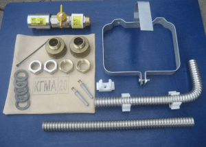
- 2 Ways to connect gas devices and fittings
- Material for the manufacture of equipment
- Classification by parameters
- Materials for production
- Let's summarize on the example of a real situation: the boiler turned off
- Safety
- Varieties of pipeline fittings
- How a gas reducer works
- Direct drive gearbox
- Reverse gear
- Scheme of switching on HBO
- carbureted engine
- Second generation on injection system
- Instructions for the 4th generation
- 1 Purpose and types of gas devices and fittings
- Types of pipeline fittings for different types of pipes
- Varieties of gas convectors
- Varieties
- Stub requirements.
- Stainless Pipe Fittings
- Basics of installation of shut-off and control equipment
- Rules for the installation of shut-off and control valves
- The nuances of equipment maintenance
Classification by various parameters
In addition to functional differences and design features, the criteria for dividing devices into groups are their purpose and scope.
By scope
According to the features of the application, the device is divided into four types:
- General purpose parts that can be used in various industries.
- Fittings for special purposes (these devices must have certain characteristics, which are specifically negotiated).
- Sanitary, which is used in pipes designed to equip household equipment.
- Shaped parts for special operating conditions, for example, for lines transporting aggressive substances.
- For pipelines of the shipbuilding or transport industry.
It is logical that fittings for gas pipelines should be distinguished by a high degree of tightness. For pipelines transporting oil, the most important is corrosion resistance, for pipes used in the chemical industry, an important criterion is inertness to aggressive chemical compounds.
By type of connection
Depending on the connection method, the reinforcement is divided into several groups:
- Flanged - collapsible parts that can be disassembled many times, for example, during repairs or for cleaning. Attaches with bolts. Common in systems operating in systems with high pressure and temperature.
- Coupling fittings with thread. Suitable for pipes made of metal-plastic, polyethylene and polypropylene tubular products.
- Reinforcement for welding - the most reliable, welding is carried out in a socket or butt.
- Tongue fittings (devices of small size that are capable of operating under high pressure, with external threads).
- Devices for choke connection (parts with external thread, with a diameter of not more than 15 mm).
According to the sealing method
Depending on how the joints are sealed, there are:
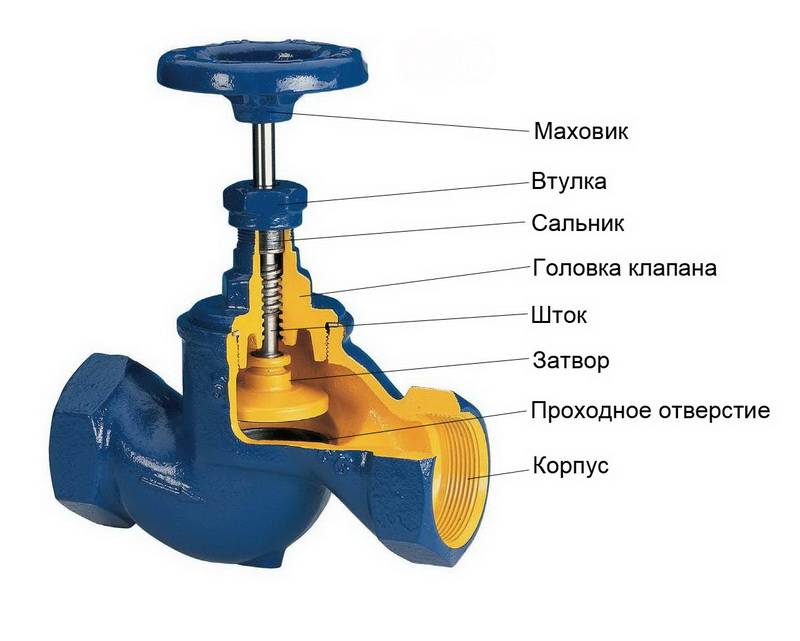
| Omental | Connection when the stem and spindle are additionally sealed with gland packing. |
| Membrane | Elastic disk that ensures the tightness of the joints. |
| Bellows | The bellows assembly, which is a corrugated tube, acts as a sealant. |
| Hose | Fittings equipped with an elastic hose, the pinching of which creates a tight shut-off of the flow. |
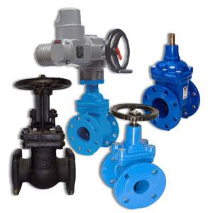
Scope of valves
Shut-off valves are designed:
- for pipelines supplying gas or water to residential, domestic and industrial premises and discharging sewage. This is the widest scope of locking devices;
- for pipelines in which aggressive substances pass. Devices for the chemical and oil and gas industries expect higher tightness and corrosion resistance;
- household networks of water supply, heat supply and sewerage. Fittings installed on private networks are small in size and easy to manage.
Only those fittings that are intended specifically for this type can be installed on the pipeline.
Characteristics and purpose
Shut-off and control valves are used in the manufacture of pipelines for water, gas and other liquids. It can be systems of water supply, heating, gas supply, sewerage.
Parts are used to regulate pressure, flow rate, carrier temperature without completely shutting down the entire line. Locking elements are installed at the branching points so that it is possible to close individual circuits at the right time.These parts have a number of technical characteristics that determine their capabilities:
- control - manual, automatic;
- throughput;
- possible adjustment of the regulator;
- regulation zone;
- stroke range of the locking mechanism;
- relative leakage.
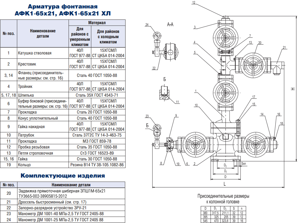
Design Specifications
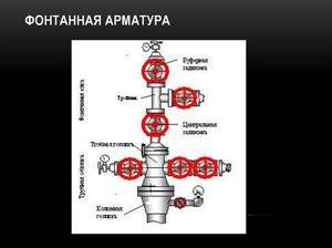 In GOST 13846–89, it was determined that Christmas trees are designed to seal wells, block the movement of the working medium and perform other technological procedures. In accordance with the standards regulated in GOST 15150–69, these devices can operate at temperatures from -60 to +40 degrees.
GOST 51365–2009 defines the technical conditions and requirements for the specified fittings. Designers involved in the construction of equipment should be guided by the requirements of this document.
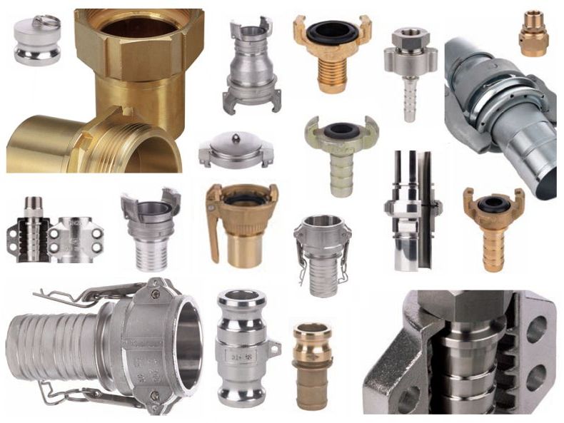
2 Ways to connect gas devices and fittings
There are the following connection methods:
- With the help of flanges - it is used for fittings, the conditional passage of which is more than 50 mm. Connection to the tank or pipeline is made using flanges. The main advantage is the possibility of multiple installation and dismantling, as well as greater strength, reliability and applicability for a very wide range of passages and pressures. Disadvantages: large weight and dimensions, over time, the possibility of loosening the tightening with subsequent loss of tightness is not ruled out.
- Union connection - for equipment with a passage of 65 mm and less. Connection is carried out using couplings having an internal thread, using a hex key.
- Tsapkovoe with an external carving. The device (for example, a faucet) is screwed with a thread directly into the body of another device or device.
- By welding - rarely used, non-separable type of connection. Advantages - reliable and complete tightness, minimum maintenance. The disadvantages include the increased complexity of replacing and installing fittings.
- Nipple - connection to a tank or pipeline is made using a nipple.
- Fitting - using a fitting.
- Coupling - the outlet and inlet pipes are connected to the pipeline flanges by means of studs with nuts located along the body of the equipment or fittings.
Material for the manufacture of equipment
The choice of material for the manufacture of such equipment depends primarily on the operating environment and functionality. For example, ceramics and glass are highly resistant to aggressive media and are used in the chemical industry. For heating systems, steel reinforcement (low-carbon or alloyed) is used, since it is heat-resistant. Also, cast iron, titanium, aluminum, brass, nickel, bronze and non-metallic materials (vinyl plastic, polyethylene, caprolactam, graphite and others) are used for manufacturing.
Noticed an error? Select it and press Ctrl+Enter
This is interesting: Methods for bending a profile pipe at home - we explain in detail
Classification by parameters
In the designation of pipeline fittings, many parameters are encrypted that determine the scope of their application and size. It is regulated by GOST R52720. The main characteristics by which the product is selected:
- Conditional pressure of the environment PN. This characteristic indicates the pressure at which the pipeline and all devices connected to it operate without failure for a certain period of time.Classification by conditional pressure is contained in GOST 26349.
- Nominal passage DN. This indicator is needed to describe piping systems for fitting various elements to each other. It is indicated in mm and is characterized by GOST 28338.
Materials for production
Gas valves are made exclusively from metal alloys. The main elements for production are cast iron, brass, bronze and steel. The use of metal elements is due to the fact that an increased level of strength is required for gas pipes and components. Polymer elements that are used in water pipes are not applicable here due to their low hardness.
Polyethylene and other materials can be easily damaged by a sharp object. And any, even the thinnest hole in the pipe will lead to gas leaks, the consequences of which have already been written. So, until a material of sufficient hardness is invented, metal elements will not give up their positions in the production of gas fittings.
As for the division of roles between metals, it all depends on the operating conditions. Brass and bronze have a high cost, so they are mainly used indoors. And steel and cast iron are used for outdoor installation. These alloys undergo a special treatment that protects them from corrosion.


Oil and gas valves include a large number of nomenclature products used in the fuel and energy industry. The market for this product is one of the most dynamically developing in the country. This is due to the high importance of oil and gas for the Russian economy as a whole.This sector of the economy has huge investments that allow it to move forward.
Let's summarize on the example of a real situation: the boiler turned off

- Check the pressure on the pressure gauge upstream of the equipment. If the pressure is normal (from 37 mbar) - the reason is the breakdown of the boiler. We need to call the repairmen. If there is no pressure, we move along the chain to the next point.
- Check the pressure after the reducer (if there is a pressure gauge). If everything is in order here, then the gas pipeline is clogged: the condensate collector is full, a plug has formed, the condensate has frozen in the basement inlet. Call experts for cleaning, blowing.
- If there is no pressure gauge or the arrow is at zero, look at the pressure gauge in front of the regulator. There must be at least 1.5 bar, otherwise the gearbox will not work. Is the pressure normal? So the problem is in the gearbox - most likely frozen. Call specialists to turn off the gas, remove, warm up and purge the regulator.
- If there is not enough pressure on the main pressure gauge, and the level gauge shows more than 15%, then most likely there has been clogging. Most of the propane is used up, and butane cannot provide the necessary pressure in cold weather. Order a delivery of propane-rich winter formula.
- If the pointer of the level gauge approaches 20–25%, it is time to call the gas carrier. Less than 15% of the liquid phase cannot be left.
Result: after checking the main points, you find the cause of the outage and take the necessary measures. In three cases, the intervention of maintenance specialists will be required, in the rest, a tanker truck with LPG will be called.
During normal use, monitor the level of the liquid phase during filling - no more than 85%. And call the gas carrier when the LPG level drops to 20-25%.
At the same time, check the pressure gauges.Such control will be enough to detect a malfunction in time. The remaining nodes are inspected by technicians during regular maintenance.
Manufacturers recommend checking the operation of the system annually. And once every 8 years, call specialists for a deeper control with an assessment of the coating, seams and the general condition of the gas tank.
How it works for us
When installing a gas tank, we conclude a contract for a year of free service. List of services: 2 preventive specialist visits (in winter and autumn) + one urgent emergency call within 24 hours. Then the service contract can be extended.
Safety
Any installation work performed with gas appliances requires the obligatory fulfillment of all safety requirements. The connected flexible hose must always be in front of your eyes. It is strictly forbidden to close it. It should always be located in a place accessible for visual inspection.
It is forbidden to use a non-standard size gas hose. They must comply with existing regulations.
The hose does not need to be painted, as paint can cause it to crack quickly. If you want to make the sleeve look prettier, you can cover it with self-adhesive paper.
The rubber sleeve is directly connected to the tap if it is located on vacation. If the thread has non-standard dimensions, an adapter is allowed.
When operating gas equipment, it is very important to comply with safety rules and existing operating standards. The fire safety of gas-fired installations depends on this.
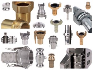
Varieties of pipeline fittings
Just as in mathematics sets are divided into subsets, types of reinforcement can be structured into varieties.
● varieties by purpose and scope
The largest of these "subsets" are varieties by purpose and application. Features of operation can be used as classification features - vacuum fittings, cryogenic fittings; or features of functioning, for example, shut-off valves (shut-off valves with a minimum response time). The basis for separation is also: the installation location (receiving fittings ─ check fittings installed at the end of the pipeline in front of the pump) and the presence of additional options (fittings with heating). But the most significant reason for dividing pipeline valves into varieties is their purpose: control valves, anti-surge valves, pressure reducing valves, drain valves, test-bleed valves, etc. The areas of application of pipe valves cannot but impose special requirements on them. The fittings used in gas facilities must be airtight due to the high fire and explosion hazard of the working medium in this case - gas. Due to the rather high chemical aggressiveness of oil, pipeline fittings for the oil-producing and oil-refining industries must have increased corrosion resistance. Even more aggressive environments, including concentrated acids and alkalis, affect pipeline fittings used in the chemical industry.
***
● varieties of connection to the pipeline
On this basis, the fittings are divided into flanged, flangeless, wafer (i.e.flangeless, installed between pipeline flanges). Coupling fittings are equipped with connecting pipes with internal thread. Fittings for welding - nozzles for welding to the pipeline. Connection fittings are also available for choke fittings.
***
● variations in the design and shaping of the body
Based on the position of the nozzles, we can talk about straight fittings (connecting pipes are coaxial or mutually parallel) or angular fittings (the axes of the inlet and outlet pipes are located perpendicular or not parallel to each other). Fittings with offset axes of branch pipes are also produced.


If the cross-sectional area of the flow part is less than the area of the opening of the inlet pipe ─ this is a non-full bore valve. If it is approximately equal to or more ─ full bore fittings. According to the method of manufacturing body parts, cast, cast-welded, litho-stamp-welded, and stamp-welded reinforcement are distinguished.
***
● varieties by type of seals
Valves in which the sealing of a stem, spindle or other moving element relative to the environment is provided by a stuffing box seal is called stuffing box valves.
Valves in which a stuffing box seal is not used for sealing are called glandless valves. Bellows and membrane fittings fall into this category.
The alphabets of most languages of the world contain several dozen letters. But this did not stop them from accumulating hundreds of thousands of words, with the use of which millions of books were written. So it is with pipe fittings ─ its incredible variety consists of a relatively small number of classification units, measured in units, sometimes tens.And it did not appear by chance, but because of the need to answer a huge number of questions, to find an algorithm for solving a large number of problems. Pipe fittings are subject to such a wide range of requirements that often the technical solutions that can be used to achieve them come into conflict with each other, and the emergence of a large number of different designs is one of the ways to overcome it. And classification is the best way not to get lost in this diversity.
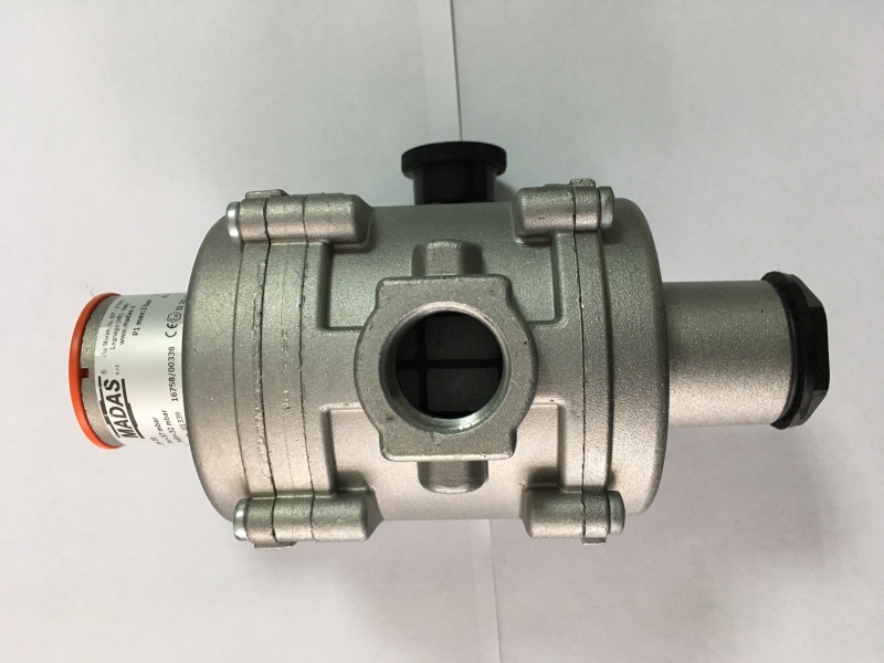
How a gas reducer works
Direct drive gearbox
Gas under high pressure from the cylinder enters the chamber, equipped with a shut-off valve. The valve under the influence of excess pressure opens and begins to abut against the seat. After that, the gas stops flowing to the outlet. The diaphragm responsible for pressure regulation, under the action of a spring, begins to displace the valve from the seat surface. The pressure is reduced due to a small passage and reaches a safe, serviceable.
Further, the straightened spring allows the valve to open access to the flow of a new volume of gas from the cylinder, and the regulation process is repeated. On non-adjustable gearboxes, the spring force is set at the factory, acting as a pressure regulator.
Reverse gear
Here the principle is somewhat different. Incoming gas from the source presses the valve against the seat, preventing it from escaping. The design contains a screw, with the help of which the spring compression force is adjusted.
By compressing the spring with a screw (regulator), the safety diaphragm is bent, passing a certain amount of gas. The support disc actuates the return spring, after which the valve rises, freeing the way for the fuel.
The working chamber has the same pressure as in the cylinder. The membrane under the action of the spring returns to its original state, and the support disk moves downward, while pressing on the return spring. As a result, the valve is pressed against the body seat.
It is worth saying that many note the great popularity of reverse action gearboxes. They are safer to use.
Scheme of switching on HBO
The selection of the generation of the gas system depends on the type of car engine. The gas-cylinder installation from the 1st to the 3rd generation is installed on both injection and carburetor machines. The modern distributed fuel supply system (4th generation) is only suitable for injection engines.
Depending on the type of internal combustion engine and the method of gas supply, the inclusion of HBO of different generations has a number of fundamental differences.
carbureted engine
The start of the ejection equipment (1,2,3 generation) on the carburetor occurs in forced mode.
The functionality of such installations allows you to start a car immediately on gas. However, in order to preserve the membrane of the evaporator reducer, it is recommended to start a cold engine (for any generation) on gasoline, especially if the ambient temperature is below 0 ° C.
To turn on gas equipment on a carburetor machine, after warming up the engine from 35 ° C and above, transfer the gas / gasoline key to the neutral position “0”.
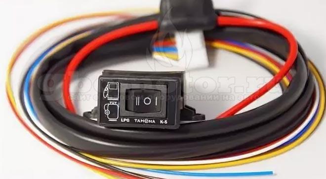
Switch for carburetor machine
So the red goes out LED on the button, indicating that the petrol valve is turned off. After that, standard fuel is produced from the float chamber of the carburetor.
Then, without waiting for the fuel starvation of the internal combustion engine (comes with experience), it is necessary to switch the toggle switch to the gas supply mode "II". The green indicator lights up, which indicates that the gas valve is turned on.
To switch back from gas to gasoline, you need to switch the key to the “I” position, bypassing the neutral position.
After stopping the internal combustion engine, the button automatically turns off the gas valve.
To start the engine on gas fuel, carburetor switches have a pre-start function. It works as follows, in the switch position "II", you need to turn on the ignition, after changing the green indicator to yellow, you can start the car.


Second generation on injection system
The gas system switch for the injector also has three positions:
- "I" - forced work on gasoline
- "0" - forced gas mode
- "II" - semi-automatic
Different manufacturers may have different order of modes.
In the semi-automatic position of the switch, the car starts immediately from gasoline fuel. This was done to warm up the power plant and the HBO gearbox, respectively. After increasing the engine speed (regassing), the car switches to gas. The number of revolutions is adjusted with a potentiometer.

Switch for injection car
Instructions for the 4th generation

Button of the fourth generation of HBO
Gas equipment of the fourth generation operates in fully automatic mode. When the HBO button is pressed, the car starts on gasoline, and after the evaporator reducer is heated, gas is turned on. The reverse transition is possible while driving by deactivating the fuel type switch.
The switching temperature is programmed when setting up the equipment.
To force the engine to start using gas, the HBO 4 system has an emergency start function.
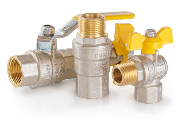
1 Purpose and types of gas devices and fittings
Gas fittings and equipment are designed for use on pipelines of transportation and supply systems, as well as distribution of blue fuel. With the help of these devices and mechanisms, the supply is switched on and off, the quantity, direction or pressure of the gas flow is changed. All fittings are characterized by the following main parameters:
- nominal (conditional) pressure;
- nominal diameter (nominal bore).
The first characteristic is understood as the maximum pressure at a temperature of 20 ° C, which ensures a long service life of various fittings (equipment) and pipeline connections. Under the conditional passage (Dn or DN) is understood the characteristic used in pipeline systems, networks as a parameter of the connected parts.
According to their purpose, fittings for gas systems are divided into the following types:
- Shut-off valves - for periodic shutdowns of equipment and devices, as well as individual sections of the gas pipeline from its other parts. In this capacity, valves, taps and gate valves are used.
- Regulating - to change and maintain pressure within specified limits. It includes dampers, gates and the like.
- Safety - used to prevent an increase in gas pressure above the permissible value. This is a relief valve.
- Cut-off and emergency - for quick automatic shutdown of various gas appliances, appliances, as well as pipelines, where the specified mode of their operation is violated. For example, a check valve.
- Reverse action - prevents the gas flow from moving in the opposite direction.
- Condensate drain - automatically removes condensate that accumulates in condensate traps and low points of pipeline networks.
Reinforcement is made from various materials. According to what the body is made of, they are designated as follows:
- of steel:
- carbonaceous - with;
- stainless - nzh;
- alloyed - hp;
- cast iron:
- gray - h;
- malleable - kch;
- bronze, brass - B;
- plastics (with the exception of vinyl plastic) - p;
- vinyl plastic - vp.
Types of pipeline fittings for different types of pipes
In order to control the flow of water or coolant, auxiliary parts are used, such as taps, gates, mixers, check valves, etc., which are capable of withstanding ambient temperatures up to +95 ° C and pressure of 16 atm. It is used when distributing pipes to plumbing, water heating, heating, plums.
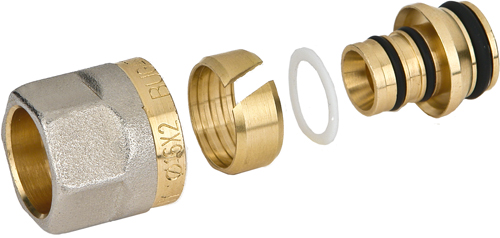
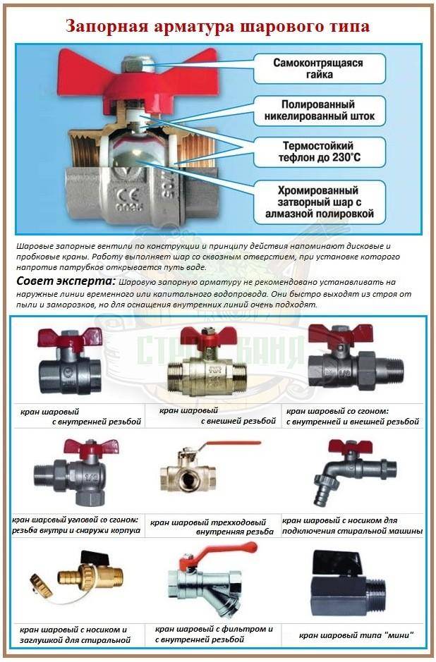
This type of pipe fittings for domestic use has significant advantages: compact, looks aesthetically pleasing, thread and press connection, symbols help in installation, and the corrosion-resistant material used for this fitting is also played an equally important role - it is nickel-plated brass . The most commonly used are various types of connecting fittings and ball valves.
Fittings for this type of pipes, such as polyethylene, are used in pressure and non-pressure systems. The most extensive list of connecting elements for welded, clamped or flanged connections. The connection of polyethylene products by welding is called one of the most reliable, it is tight and forms a single structure.
The regulation of the flow of the working medium of such pipelines occurs by means of non-corrosive polyethylene (HDPE) or brass taps, dampers, valves designed for pressure up to 16 atm and a flow temperature of +45 ... +80 ° С (hot water supply). Polyethylene ball valves can be deformed if the temperature regime is not observed.
For polypropylene pipes.
The pipeline shut-off and control system, as well as various types of connecting pipeline fittings for polypropylene pipes are the same as for previous polyethylene pipes. Such fittings are designed for pressure up to 20 atm, working medium temperature up to +90 °С. At present, a significant number of manufacturers have begun to produce models of polypropylene elements with a clip made of hot-pressed nickel-plated brass - it is a one-piece structure with sufficient resistance to thermal deformation.


Brass threaded collapsible connections in polypropylene fittings make it possible to equip a plastic pipeline with metal fittings. Such polyethylene and polypropylene additional parts are much cheaper than similar metal ones.
Read related material:
Autonomous heating pipes
Varieties of gas convectors
Today on the market you can find a variety of designs of convectors operating on main gas, which differ from each other:
- By type of material: steel and cast iron.
- By type of installation: wall, floor, ceiling. The latter are used for heating large industrial and commercial facilities.
- By power: small, medium and large. Such devices function effectively only in separate rooms.The load is selected from the ratio of 1.0 kW per 10.0 m2. It is easy to calculate that for 80 m2 it is necessary to choose a device with a power of 8 kW.
- By type of combustion chamber: open and closed, which differ in the chimney system. For devices of the first type, exhaust gases are removed through a stationary chimney, equipped according to the furnace principle in the inter-wall space, which requires additional funds for installation. Models of the second option are easier to install. The exhaust air is removed to the atmosphere through a coaxial pipe.
Varieties
Pipe fittings are classified depending on various factors. By purpose:
- Safety. Protect lines from sudden pressure drops. Thanks to automation, excess pressure is released.
- Locking. Designed to block the flow of liquid or gas. They work in two positions - closed, open.
- Connecting. More often it has union nuts, which simplify the connection process.
- regulatory mechanisms. By design, they are similar to shut-off parts, but they can regulate the intensity of the supply of liquid, gas.
- Distribution. Designed to connect additional circuits to a common trunk, create separate branches.
Types of pipeline fittings, depending on the design:
- Gate valves - suitable for installation on circuits with low pressure of the working medium. They only work in the closed/open position. To change the position, you need to use a special valve that needs to be turned.
- Valves - shut-off, control valves.Allows you to completely block the flow of liquid or regulate it. The position is changed manually by turning the knob.
- Valves are parts that shut off flow when pressure increases. They can be installed in those places where it is necessary to change the direction of fluid flow.
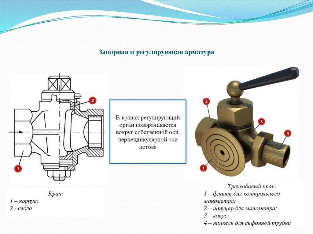
- Cranes are designs that are suitable for adjusting, shutting off, changing the direction of the flow of the working medium. Used to assemble liquid and gas supply lines.
A separate group of valves - gate valves. Installed on industrial highways. They are classified depending on the design, the principle of action on flanges, gate valves.
Depending on the method of sealing, three more types of structures are distinguished:
- Gland fittings. There is a stuffing box inside. Thanks to her, the spindle is compacted.
- Bellows details. A bellows is used for sealing.
- Membrane armature.
Connecting parts are classified according to the method of control. They can be manual or automatic.
Stop valves ( / sanremo67)
Stub requirements.
Since fittings with tightness not lower than class “B” are used, metal plugs are installed after closing the shut-off valves to hermetically close the gas flow to consumers.
Firstly, the plugs are flat (metal-sheet).
Secondly, the plugs are threaded.
Flat plugs are usually made of steel, the thickness of the plug is calculated depending on the gas pressure and DN (nominal diameter). Plug diameter = flange face diameter. The plug must moreover have a shank protruding from the flange, on which the pressures (P) and (DN) are recorded.
For example, a number of nominal diameters corresponding to them pipe thread in inches and D flange mirror.
| DN(mm) | G (in inches) | D c.f. (mm) |
| 15 | 1/2″ | – |
| 20 | 3/4″ | – |
| 25 | 1″ | 60 |
| 32 | 1 1/4″ | 70 |
| 40 | 1 1/2″ | 80 |
| 50 | 2″ | 90 |
| 65 | 2 1/2″ | – |
| 70 | – | 110 |
| 80 | – | 128 |
| 100 | – | 148 |
| 125 | – | 178 |
| 150 | – | 202 |
| 200 | – | 258 |
| 250 | – | 312 |
| 300 | – | 365 |
Stainless Pipe Fittings
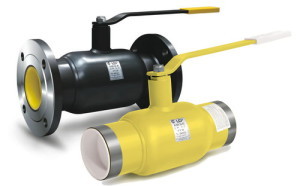
Industrial shut-off valves made of stainless steel are indispensable for the transportation of many working media. It is very durable, inert to aggressive substances, resistant to dangerously high temperatures and pressures, has good wear resistance, and does not corrode. Given these characteristics, it is not surprising that the mechanisms of this material have become the main working units in the oil and gas, pharmaceutical, food and chemical industries. Stainless fittings are also widely used at nuclear power plants.
It is clear that such mechanisms can be used both in heating systems and in domestic systems that supply objects with water and heat.
Basics of installation of shut-off and control equipment
No pipeline can fully function without shut-off equipment. Due to the fact that there are several varieties of it, the installation of one of them differs significantly from the installation of other devices and should only be carried out by specialists using specialized equipment.
The operability, durability and safety of the pipeline depend on how skillfully the installation work was carried out.
The fittings are connected to the pipeline:
- couplings with internal thread;
- pins on the outer seal;
- nipples;
- flanges;
- welding.
Welding is the most reliable method of mutual fastening of pipeline elements and the only one that is suitable for transporting high pressure media.
Connection with flanges, flat rings or disks of alloy steel, bolted to the ends of the parts to be fixed, also provides the required tightness. Manufacturers of valves provide a guarantee for their products by testing the impermeability and strength of parts, their compliance with technical requirements.
Rules for the installation of shut-off and control valves
There are several important rules that should be observed when installing shut-off and control valves:
1. Mandatory cleaning of the pipeline. After the parts have been transported, they must be processed manually or by exposure to air, steam or water. When welding, it is also necessary to regularly inspect the pipe for contamination so that the scale formed does not damage the tightness.


2. Check flanges for unevenness. The smooth surface of the part must not be scratched or have other pronounced defects.
3. Avoid installing shut-off valves in areas with uneven terrain. If the mechanism is not located on a straight section of the pipeline, the stress that occurs at the bends will affect the tightness and provoke leaks.
4. Shielding against pressure surges that occur during water hammer, which can damage or disable the entire system, including fittings, is carried out by installing a check valve to ensure a stable flow.
5. Large diameter valves or heavy actuators may require additional support to prevent breakage of screws or gaskets.
6. Valves can be damaged if too much force is applied to tighten them.
7.The stainless steel fitting must be in the open position during installation.
The nuances of equipment maintenance
According to the schedule developed by the engineer of the gas supply company, the condensate collectors are purged and their technical condition is checked. These jobs are considered dangerous because the condensate contains not only water, but also highly flammable liquid butane, which often makes up the majority of the liquid. Therefore, two specialists carry out maintenance, only during the day, not during a thunderstorm.
It is also forbidden to drain condensate directly into a tank truck - only into metal stationary tanks with a fence or into a pit. If there is an oil pipeline nearby, condensate can be drained into it.
To empty the low pressure condensate trap, you will need a pump, motor pump or vacuum tank. Remove the plug from the end of the tube, connect the pump hose to it, open the tap and start the pump. Pumping continues until the liquid stops flowing from the pump, and then it is turned off, the valve is closed, the hose is disconnected and the plug is returned to its place.
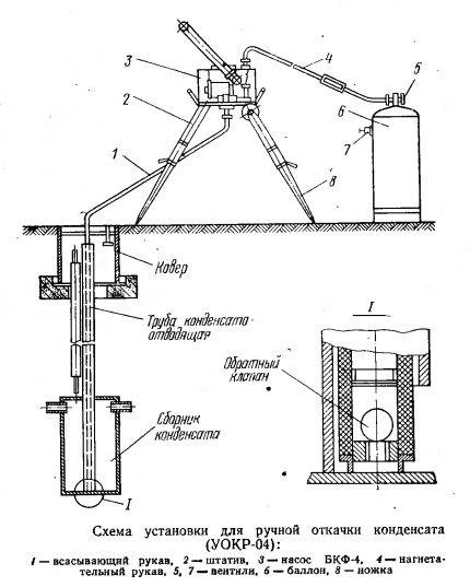 A small condensate trap can be handled with a hand pump, and some above-ground models drain off by gravity
Medium and high pressure condensate collectors a pump is usually not needed. They have 2 risers: with condensate and with gas, each has a tap, and usually only the one on gas is open.
To free the tank from the liquid, both valves are turned: the gas valve is closed, and the condensate valve is opened. The liquid comes out under the pressure of the gas from the line.To save time and labor, this process can be automated through instrumentation and automation.
If the condensate is not removed in time, a water hammer or plug can not only prevent the gas supply, but also damage the pipe.
In addition to removing the collected condensate, gas pipeline crawlers check the presence and accuracy of the plates indicating their location, as well as the serviceability of the unit itself and the associated shut-off valves. If necessary, repairs are carried out immediately or an act is drawn up, according to which a special team subsequently leaves.