- Tips for mounting magnetic starters
- MP connection diagram
- Scheme with connecting a 220 volt coil
- Working Principle
- How to connect a thermal relay?
- Relay operation
- Installation of starters inside the electrical panel
- 9 comments
- Connection process
- Wiring diagrams
- Star-delta circuit
- 220 volt coil: wiring diagrams
- Connection to the network 220 V
- Using the Start and Stop Buttons
- Connection diagrams for a magnetic starter with a 220 V coil
- Connecting a starter with a 220 V coil to the network
- Scheme with "start" and "stop" buttons
- Domestic models of popular starters
- Other articles in the section: Electrical installation at home
Tips for mounting magnetic starters
When installing magnetic starters with thermal relays, it is necessary to install with a minimum ambient temperature difference between the electric motor and the magnetic starter.
It is undesirable to install magnetic devices in places subject to strong shocks or vibrations, as well as near powerful electromagnetic devices whose currents exceed 150 A, since they create quite large shocks and shocks when triggered.
For normal operation of the thermal relay, the ambient temperature should not exceed 40 0 С.It is also not recommended to install near heating elements (rheostats) and not to install them in the most heated parts of the cabinet, for example, at the top of the cabinet.
Comparison of magnetic and hybrid starter:
Magnetic starters
they are mainly used for starting, stopping and reversing three-phase asynchronous electric motors, however, due to their unpretentiousness, they work great in remote control circuits for lighting, in control circuits for compressors, pumps, overhead cranes, thermal furnaces, air conditioners, conveyor belts, etc. d. In a word, the magnetic starter has a wide range of applications.
As such, the magnetic starter is already difficult to find in stores, as they have practically been replaced contactors
. Moreover, in terms of its design and technical characteristics, a modern contactor is no different from a magnetic starter, and they can only be distinguished by name. Therefore, when you buy a starter in a store, be sure to specify that it is a magnetic starter or contactor.
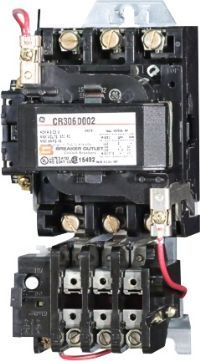
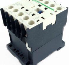
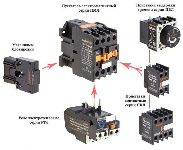
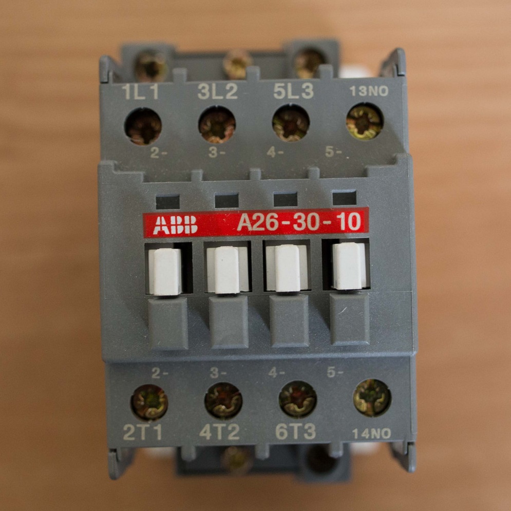
We will consider the device and operation of a magnetic starter using the example of a type contactor KMI
– small-sized alternating current contactor for general industrial use.
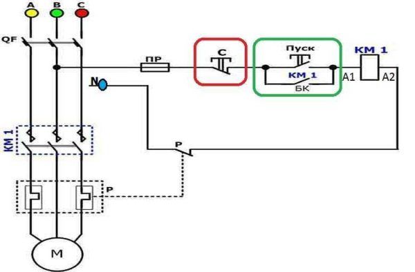
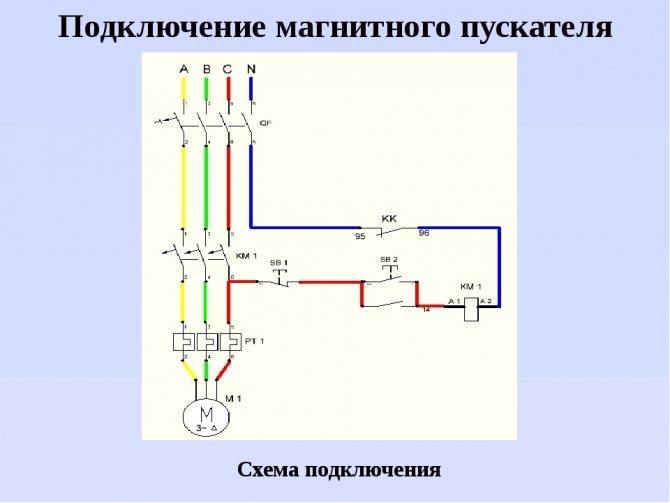
MP connection diagram
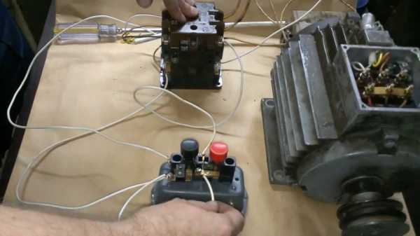
A popular scheme for connecting a magnetic starter through a push-button post.
The main circuit has two parts:
Our readers recommend!
To save on electricity bills, our readers recommend the Electricity Saving Box. Monthly payments will be 30-50% less than they were before using the saver. It removes the reactive component from the network, as a result of which the load and, as a result, the current consumption are reduced.Electrical appliances consume less electricity, reducing the cost of its payment.
- Three pairs of power contacts direct electrical power to electrical equipment.
- A graphical representation of the control, which is made up of a coil, buttons and additional contactors that take part in the operation of the coil or do not allow erroneous switching on.
The most common is the single device wiring diagram. She is the easiest to deal with. To connect its main parts, you need to take a three-core cable and a pair of open contactors when the device is turned off.
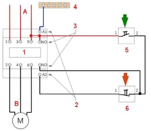
Scheme with connecting a 220 volt coil
Analyze the design with a voltage of 220 volts. If the voltage is 380 volts, instead of a blue zero, you need to connect a phase of a different kind. In this situation, black or red. In case of blocking the contactor, the fourth pair is taken, which works with 3 power pairs. They are in the upper part, but the side ones are located on the side.
3 phases A, B and C are supplied to pairs of power contactors from the machine. To turn on when you touch the "Start" button, it is necessary that the voltage is 220 V on the core, which will help the movable contactors connect to those that are stationary. The circuit will begin to close, in order to disconnect it, you need to disconnect the coil.
To assemble the control circuit, you need to connect one phase directly to the core, and connect the second phase with a wire to the start contact.
From the 2nd contactor, we lay 1 more wire through the contacts to another open contact of the Start button. A blue jumper is made from it to the closed contactor of the "Stop" button, zero from the electrical supply is connected to the 2nd contactor.


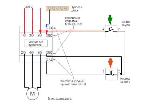


Working Principle
The principle of operation is simple.If you press the "Start" button, its contacts begin to close and a voltage of 220 volts goes to the core - it starts the main and side contacts and an electromagnetic flux occurs. If the button is released, the contactors of the start button open, but the device is still on, since zero is transmitted to the coil through the closed blocking contacts.
In order to turn off the MP, you need to break the zero by opening the contacts of the Stop button. The device will not turn on again, because the zero will be broken. To turn it on again, you will need to press "Start".
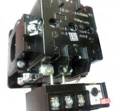
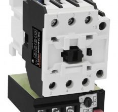
How to connect a thermal relay?
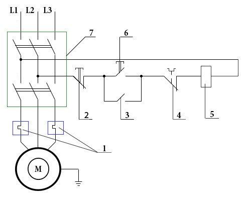
You can also draw up a one-line graphical drawing of connecting a three-phase electric motor to a magnetic starter through a relay.
A relay is connected in series between the MP and an asynchronous electric motor, which is selected depending on the specific type of motor. This device protects the motor from breakdowns and emergency mode (for example, when one of the three phases disappears).
The relay is connected to the output from the MP to the electric motor, electricity passes in it in a sequential manner through the heating of the relay to the electric motor. On top of the relay are auxiliary contactors, which are combined with the coil.
Relay operation
Thermal relay heaters are designed for the maximum value of the current that passes through them. When the current rises to unsafe limits for the motor, the heaters turn off the MP.
Installation of starters inside the electrical panel
MP design allows installation in the middle of the electrical panel. But there are rules that apply to all devices. To ensure high reliability of operation, it is necessary that the installation is carried out on an almost straight and solid plane.Moreover, it is located vertically on the wall of the electrical panel. If there is a thermal relay in the design, then it is necessary that the temperature difference between the MP and the electric motor be as small as possible.
9 comments
The main circuit has two parts: Three pairs of power contacts direct electrical power to electrical equipment. Switching off the magnetic starter in this case is possible only when the control coil circuit is broken, from which it becomes obvious that a button with a NC contact must be used.
And it cannot be adjusted exactly to the rated current of the motor. For example, you can supply power to the coil through a time relay or a light sensor, and connect a street lighting power line to the contacts.
Device and principle of operation In order to better understand the connection diagrams of a magnetic starter, it is necessary to understand its device and principle of operation.
Each of them has a pair of inputs and a pair of outputs. Magnetic starter connection diagram Magnetic starter is a low voltage electromagnetic combined device for distribution and control, designed to start and accelerate various electric motors.
Recommended: How to repair the wiring in the apartment
It is also impossible to install the MP in the same room with devices that have a current higher than A. Now, if it is released, the magnetic starter continues to work until the voltage disappears or the thermal relay R of the motor protection trips.
It is shown in detail in what sequence it is better to connect the wires in the next video. Phase A does not change.There is also usually a ground connection terminal. Now you can connect the wires or cables of the power circuit, not forgetting that next to one of them at the input there is a wire to the control circuit.
Contactors have powerful arc chutes. The contacts are closed, the load is energized, as a result, it is included in the work. Scheme with coil connection per volt Analyze the design with voltage per volt.
Therefore, in production, winding switching is used to start especially powerful electric motors. As a result, the motor M will change the direction of rotation. Buttons for controlling the electric motor are part of the push-button posts, push-button posts can be single-button, two-button, three-button, etc. An electromagnet in the form of a coil with a large number of turns is designed for a voltage of 24 - V. In this case, power is supplied using two phases L2 and L3, while in the first case - L3 and zero.
How to connect a magnetic starter PME - 071 - 380 volts - How to connect a magnetic starter
Connection process
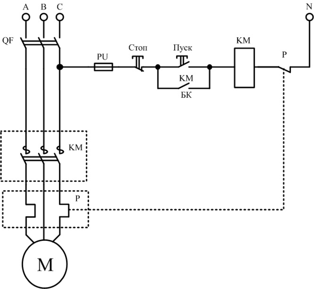
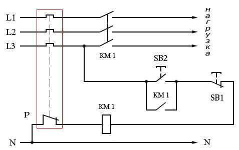
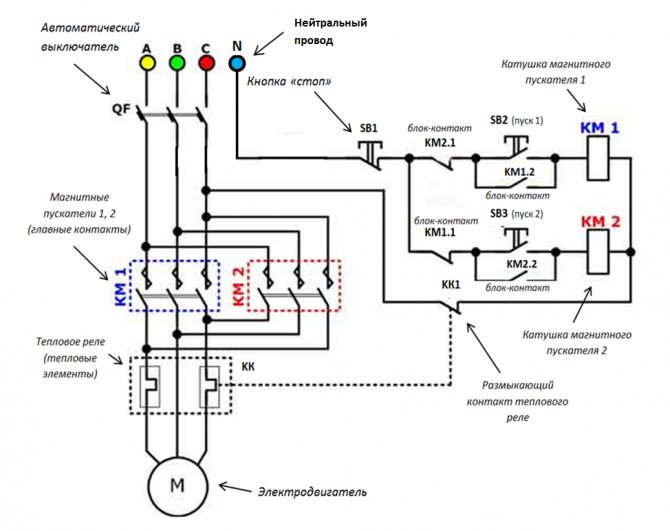
Below is a connection diagram of the TR with symbols. On it you can find the abbreviation KK1.1. It denotes a contact that is normally closed. The power contacts through which the current flows to the motor are indicated by the abbreviation KK1. The circuit breaker located in the TR is designated as QF1. When it is activated, power is supplied in phases. Phase 1 is controlled by a separate key, which is marked SB1. It performs an emergency manual stop in case of an unexpected situation. From it, the contact goes to the key, which provides a start and is indicated by the abbreviation SB2.The additional contact, which departs from the start key, is in the standby state. When starting is performed, then the current from the phase through the contact enters the magnetic starter through the coil, which is designated KM1. The starter is triggered. In this case, those contacts that are normally open are closed and vice versa.
When the contacts are closed, which are abbreviated KM1 in the diagram, then three phases are turned on, which let current through the thermal relay to the motor windings, which is put into operation. If the current strength increases, then due to the influence of the contact pads TP under the abbreviation KK1, three phases will open and the starter will be de-energized, and the motor will stop accordingly. The usual stop of the consumer in forced mode occurs by acting on the SB1 key. It breaks the first phase, which will stop the voltage supply to the starter and its contacts will open. Below in the photo you can see an impromptu wiring diagram.
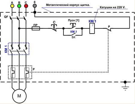
There is another possible connection scheme for this TR. The difference lies in the fact that the relay contact, which is normally closed when triggered, does not break the phase, but zero, which goes to the starter. It is used most often due to cost-effectiveness when performing installation work. In the process, the neutral contact is connected to the TR, and a jumper is mounted from the other contact to the coil, which starts the contactor. When the protection is triggered, the neutral wire opens, which leads to the disconnection of the contactor and the motor.
The relay can be mounted in a circuit where the reverse movement of the motor is provided.From the diagram that was given above, the difference is that there is an NC contact in the relay, which is designated KK1.1.
If the relay is activated, then the neutral wire breaks with contacts under the designation KK1.1. The starter de-energizes and stops powering the motor. In an emergency, the SB1 button will help you quickly break the power circuit to stop the engine. You can watch a video about connecting the TR below.
Wiring diagrams
Let's start by considering the design of a three-phase electric motor. Here we will be interested in three windings, which create a magnetic field that rotates the rotor of the motor. That is, this is how the conversion of electrical energy into mechanical energy occurs.
There are two connection schemes:
Immediately make a reservation that the connection with a star makes the start-up of the unit smoother. But at the same time, the power of the electric motor will be lower than the nominal value by almost 30%. In this regard, the triangle connection wins. The motor connected in this way does not lose power. But there is one caveat that concerns the current load. This value increases sharply at start-up, which negatively affects the winding. The high current in the copper wire increases thermal energy, which affects the insulation of the wire. This can lead to insulation breakdown and failure of the motor itself.
I would like to draw your attention to the fact that a large number of European equipment brought to the expanses of Russia is equipped with European electric motors that operate at a voltage of 400/690 volts. By the way, below is a photo of the nameplate of such a motor
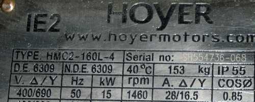
So these three-phase electric motors must be connected to the domestic 380V network only according to the triangle scheme.If you connect a European motor with a star, then under load it will immediately burn out. Domestic three-phase electric motors are connected to a three-phase network according to the star scheme. Sometimes the connection is made in a triangle, this is done in order to squeeze the maximum power out of the motor, which is necessary for some types of technological equipment.
Manufacturers today offer three-phase electric motors, in the connection box of which conclusions of the ends of the windings are made in the amount of three or six pieces. If there are three ends, then this means that a star connection diagram has already been made at the factory inside the motor. If there are six ends, then a three-phase motor can be connected to a three-phase network with both a star and a triangle. When using the star circuit, it is necessary to connect the three ends of the beginning of the windings in one twist. Connect the other three (opposite) to the phases of the supply three-phase network 380 volts. When using the triangle scheme, you need to connect all the ends together in order, that is, in series. The phases are connected to three points of connection of the ends of the windings to each other. Below is a photo showing two types of connecting a three-phase motor.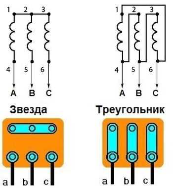
Star-delta circuit
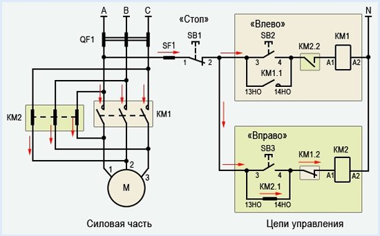
Such a scheme for connecting to a three-phase network is used quite rarely. But it exists, so it makes sense to say a few words about it. What is it used for? The whole point of such a connection is based on the position that when starting the electric motor, a star circuit is used, that is, a soft start, and a triangle is used for the main work, that is, the maximum power of the unit is squeezed out.
True, such a scheme is quite complicated.In this case, three magnetic starters are necessarily installed in the connection of the windings. The first is connected to the mains on one side, and on the other side, the ends of the windings are connected to it. The opposite ends of the windings are connected to the second and third. The second starter is connected by a triangle, to the third by a star.
Attention! It is impossible to turn on the second and third starters at the same time. There will be a short circuit between the phases connected to them, which will lead to the reset of the machine
Therefore, a lock is established between them. In fact, everything will happen like this - when one is turned on, the contacts of the other open.


The principle of operation is as follows: when the first starter is turned on, the time relay also turns on starter number three, that is, the star connected according to the scheme. There is a soft start of the electric motor. The time relay sets a certain period during which the motor will switch to normal operation. After that, starter number three turns off, and the second element turns on, transferring the triangle to the circuit.
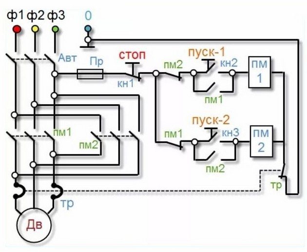
220 volt coil: wiring diagrams
To control the operation of the magnetic starter, only two buttons are used - the "Start" button and the "Stop" button. Their execution may be different: in a single housing or in separate housings.
Buttons can be in the same housing or in different
Buttons produced in separate housings have only 2 contacts each, and buttons produced in one housing have 2 pairs of contacts. In addition to contacts, there may be a terminal for connecting the ground, although modern buttons are produced in protected cases that do not conduct electricity.There are also push-button posts in a metal case for industrial needs, which are distinguished by high impact resistance. As a rule, they are grounded.
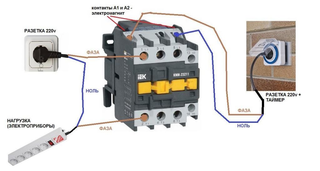
Connection to the network 220 V
Connecting a magnetic starter to a 220 V network is the simplest, so it makes sense to start familiarizing yourself with these circuits, which may be several.
The voltage of 220 V is supplied directly to the magnetic starter coil, which are designated as A1 and A2 and which are located in the upper part of the housing, as can be seen from the photo.
Connecting a contactor with a 220 V coil
When a conventional 220 V plug with a wire is connected to these contacts, the device will start working after the plug is plugged into a 220 V socket.
With the help of power contacts, it is permissible to turn on / off the electrical circuit for any voltage, so long as it does not exceed the permissible parameters indicated in the product passport. For example, a battery voltage (12 V) can be applied to the contacts, with the help of which a load with an operating voltage of 12 V will be controlled.
It should be noted that it does not matter which contacts are supplied with a single-phase control voltage, in the form of "zero" and "phase". In this case, the wires from contacts A1 and A2 can be swapped, which will not affect the operation of the entire device. It is quite natural that such a switching circuit is used extremely rarely, since it requires a direct supply of voltage to the magnetic starter coil
At the same time, there are many options for switching on, using a time relay or a twilight sensor, by connecting street lighting to power contacts, for example. The main thing is that "phase" and "zero" are nearby
It is quite natural that such a switching circuit is used extremely rarely, since it requires a direct supply of voltage to the magnetic starter coil. At the same time, there are many options for switching on, using a time relay or a twilight sensor, by connecting street lighting to power contacts, for example. The main thing is that the "phase" and "zero" are nearby.
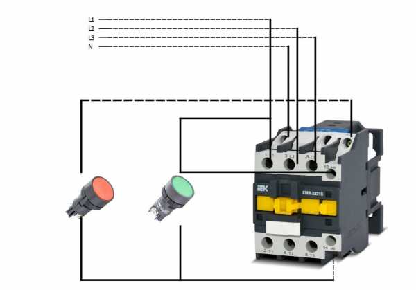
Using the Start and Stop Buttons
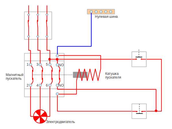
Basically, magnetic starters are involved in the operation of electric motors. Without the presence of the "Start" and "Stop" buttons, such work is associated with a number of difficulties. First of all, this is due to the peculiarities of the operation of electric motors, which are often located at a considerable distance. The buttons are connected to the coil circuit in series, as in the figure below.
Scheme of switching on a magnetic starter with buttons
This method is characterized by the fact that the magnetic starter will be in working condition as long as the "Start" button is pressed, which is very inconvenient. In this regard, additional (BC) contacts of the magnetic starter are included in the circuit, which duplicate the operation of the Start button. When the magnetic starter is turned on, they close, therefore, after releasing the "Start" button, the circuit remains operational. They are marked on the diagram as NO (13) and NO (14).
Connection diagram of a magnetic starter with a 220 V coil and a self-pickup circuit
You can turn off the running equipment only with the help of the "Stop" button, which breaks the electrical supply circuit of the magnetic starter and the entire circuit. If the circuit provides for other protection, for example, thermal, then if it is triggered, the circuit will also be inoperative.
Power for the motor is taken from the contacts T, and power is supplied to the contacts of the magnetic starter, under the designation L.
This video explains in detail and shows in what sequence all the wires are connected. In this example, a button (button post) is used, made in one housing. As a load, you can connect a measuring device, an ordinary incandescent lamp, a household appliance, etc., operating from a 220 V network.


How to connect a magnetic starter. Connection diagram.
Watch this video on YouTube
Connection diagrams for a magnetic starter with a 220 V coil
Before we move on to the diagrams, let's figure out what and how these devices can be connected. Most often, two buttons are required - “start” and “stop”. They can be made in separate cases, or there may be a single case. This is the so-called button post.
Buttons can be in the same housing or in different
With separate buttons, everything is clear - they have two contacts. Power is supplied to one, it leaves the second. There are two groups of contacts in the post - two for each button: two for start, two for stop, each group on its own side. There is also usually a ground connection terminal. Nothing complicated either.
Connecting a starter with a 220 V coil to the network
Actually, there are many options for connecting contactors, we will describe a few. The scheme for connecting a magnetic starter to a single-phase network is simpler, so let's start with it - it will be easier to figure it out further.
Power, in this case 220 V, relies on the coil leads, which are labeled A1 and A2. Both of these contacts are located in the upper part of the case (see photo).
Here you can supply power to the coil
If you connect a cord with a plug to these contacts (as in the photo), the device will be in operation after the plug is inserted into the socket. At the same time, any voltage can be applied to the power contacts L1, L2, L3, and it will be possible to remove it when the starter is triggered from the contacts T1, T2 and T3, respectively. For example, inputs L1 and L2 can be supplied with a constant voltage from the battery, which will power some device that will need to be connected to the outputs T1 and T2.
Connecting a contactor with a 220 V coil
When connecting single-phase power to the coil, it does not matter which output to apply zero, and which phase. You can switch wires. Even more often, a phase is supplied to A2, since for convenience this contact is also brought out on the bottom side of the case
And in some cases it is more convenient to use it, and connect "zero" to A1
Even more often, a phase is supplied to A2, since for convenience this contact is also brought out on the underside of the case. And in some cases it is more convenient to use it, and connect “zero” to A1.
But, as you understand, such a connection scheme for a magnetic starter is not particularly convenient - you can also directly supply conductors from the power source by integrating a conventional knife switch. But there are much more interesting options. For example, you can supply power to the coil through a time relay or a light sensor, and connect a street lighting power line to the contacts. In this case, the phase starts at the L1 contact, and zero can be taken by connecting to the corresponding coil output connector (in the photo above it is A2).
Scheme with "start" and "stop" buttons
Magnetic starters are most often set to turn on the electric motor. It is more convenient to work in this mode if there are “start” and “stop” buttons.They are connected in series to the phase supply circuit to the output of the magnetic coil. In this case, the circuit looks like the figure below.
note that
Scheme of switching on a magnetic starter with buttons
But with this method of switching on, the starter will only work for as long as the “start” button is held down, and this is not what is required for long-term engine operation. Therefore, the so-called self-pickup circuit is added to the circuit. It is implemented using auxiliary contacts on the starter NO 13 and NO 14, which are connected in parallel with the start button.
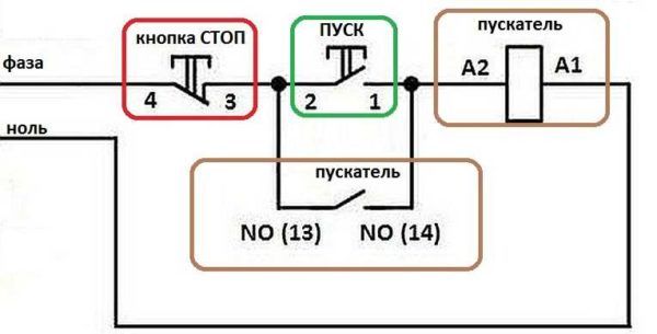

Connection diagram of a magnetic starter with a 220 V coil and a self-pickup circuit
In this case, after the START button returns to its original state, power continues to flow through these closed contacts, since the magnet has already been attracted. And power is supplied until the circuit is broken by pressing the "stop" key or by triggering a thermal relay, if there is one in the circuit.
Power for the motor or any other load (phase from 220 V) is supplied to any of the contacts marked with the letter L, and is removed from the contact located below it marked T.
It is shown in detail in what sequence it is better to connect the wires in the next video. The whole difference is that not two separate buttons are used, but a button post or a button station. Instead of a voltmeter, it will be possible to connect an engine, a pump, lighting, any device that operates on a 220 V network.
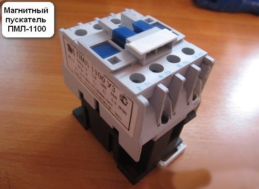
Domestic models of popular starters
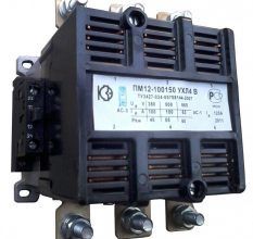
In the classification of starters, starters are most popular: PMA, PME, PM 12. About them and how to choose a magnetic starter in the following articles.
Other articles in the section: Electrical installation at home
- Basic standards for electrical work
- Introductory machine.Calculation, selection of an introductory machine for an apartment
- Paper insulated cables
- Cable metal tray
- How to choose a stylish floor lamp
- How to properly install electrical wiring in the bath
- How to reduce the cost of electrical work
- Complete set of switchboard, circuit breakers, connection terminals
- Magnetic starters: purpose, connection diagram
- Installation of electrical wiring