- The device and operation of the electrothermal relay.
- Types of signal relay
- Pointer relay - marking
- So, let's start with the most difficult. What to do if the passport data of the engine is not known?
- TABLE FOR THE SELECTION OF THERMAL RELAYS
- The main types of relays and their purpose
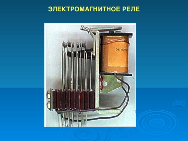
- Electromagnetic relays
- AC relay
- DC relay
- Electronic relay
- Main types and technical characteristics of electromagnetic relays
- Contact and non-contact
- By scope
- According to the power of the control signal
- By control speed
- By type of control voltage
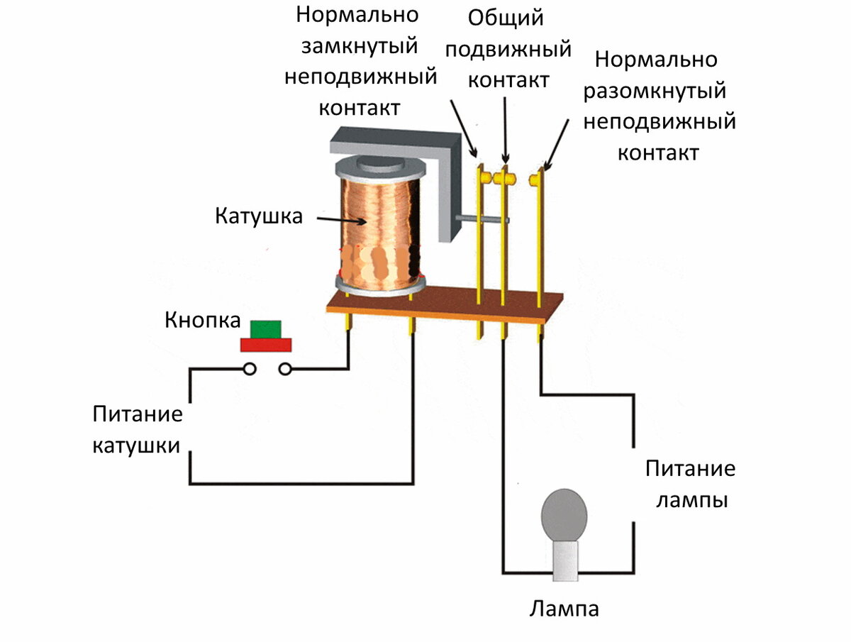
- General relay device
- Product parameters
- Mounting Features
- Types of EMR
- Types and types of electrical circuits
- Conclusions and useful video on the topic
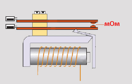
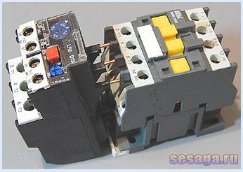
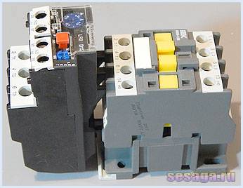
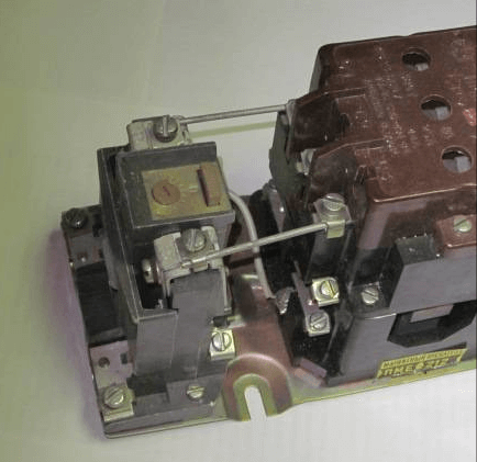
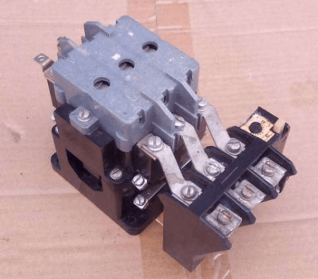
The device and operation of the electrothermal relay.
The electrothermal relay works complete with a magnetic starter. With its copper pin contacts, the relay is connected to the output power contacts of the starter. The electric motor, respectively, is connected to the output contacts of the electrothermal relay.
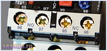
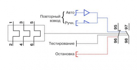
Inside the thermal relay there are three bimetallic plates, each of which is welded from two metals with a different coefficient of thermal expansion.The plates through a common "rocker" interact with the mechanism of the mobile system, which is connected with additional contacts involved in the motor protection circuit:
1. Normally closed NC (95 - 96) are used in starter control circuits; 2. Normally open NO (97 - 98) are used in signaling circuits.
The principle of operation of the thermal relay is based on deformations bimetallic plate when it is heated by a passing current.
Under the influence of the flowing current, the bimetallic plate heats up and bends towards the metal, which has a lower coefficient of thermal expansion. The more current flows through the plate, the more it will heat up and bend, the faster the protection will work and turn off the load.
Assume that the motor is connected via a thermal relay and is operating normally. At the first moment of operation of the electric motor, the rated load current flows through the plates and they heat up to the operating temperature, which does not cause them to bend.
For some reason, the load current of the electric motor began to increase and a current flowing through the plates exceeded the nominal one. The plates will begin to heat up and bend more strongly, which will set in motion the mobile system and it, acting on the additional relay contacts (95 – 96), will de-energize the magnetic starter. As the plates cool down, they will return to their original position and the relay contacts (95 – 96) will close. The magnetic starter will again be ready to start the electric motor.
Depending on the amount of current flowing in the relay, a current trip setting is provided, which affects the plate bending force and is regulated by a rotary knob located on the relay control panel.
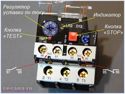
In addition to the rotary control on the control panel there is a button "TEST”, designed to simulate the operation of the relay protection and check its performance before being included in the circuit.
«Indicator» informs about the current state of the relay.
Button "STOP» the magnetic starter is de-energized, but as in the case of the «TEST» button, the contacts (97 – 98) do not close, but remain in the open state. And when you use these contacts in the signaling circuit, then consider this moment.
The electrothermal relay can work in manual or automatic mode (default is automatic).
To switch to manual mode, turn the rotary button "RESET» counterclockwise, while the button is slightly raised.
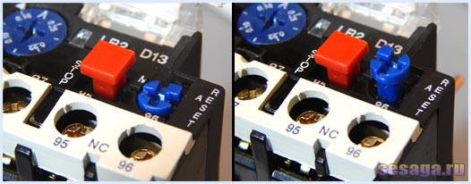
Suppose that the relay has worked and de-energized the starter with its contacts. When operating in automatic mode, after the bimetallic plates have cooled down, the contacts (95 — 96) and (97 — 98) will automatically go to the initial position, while in manual mode, the transfer of contacts to the initial position is carried out by pressing the button "RESET».
In addition to email protection. motor from overcurrent, the relay provides protection in the event of a power phase failure. For example. If one of the phases breaks, the electric motor, working on the remaining two phases, will consume more current, which will cause the bimetallic plates to heat up and the relay will work.
However, the electrothermal relay is not able to protect the motor from short-circuit currents and itself needs to be protected from such currents. Therefore, when installing thermal relays, it is necessary to install automatic switches in the power supply circuit of the electric motor that protect them from short circuit currents.
When choosing a relay, pay attention to the rated load current of the motor, which will protect the relay. In the instruction manual that comes in the box, there is a table according to which a thermal relay is selected for a specific load:
For example, the RTI-1302 relay has a setting current adjustment limit from 0.16 to 0.25 Amperes. This means that the load for the relay should be selected with a rated current of about 0.2 A or 200 mA.


Types of signal relay
There are the following types of indicator relays: open; closed; switching. They come with a constant or variable current characteristic. In this case, the DC relay can be: neutral, polarized, combined.
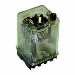 Modern indicator relay
Neutral relays detect the presence and absence of a control signal. Polarized devices respond to the polarity of the control signal. In this case, if the polarity is reversed, the relay switches. Combined types combine the two types described above, respond to polarity and signal.
By design features, the indicator relay can be divided into two subgroups: static and electromechanical. Static are ionic, microprocessor, ferromagnetic, semiconductor. Electromechanical relays can be magnetoelectric, induction, electromagnetic, thermal, electrodynamic.
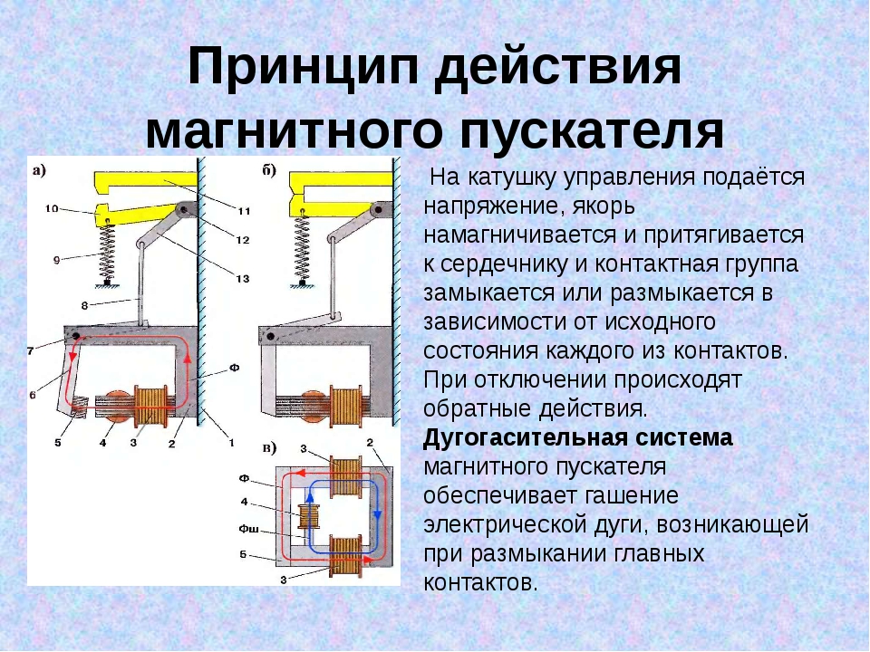
Electromagnetic types have a magnetic design and a coil that is located on its fixed part. In addition, the design has an armature, which has a connection with closed and open contacts. When voltage is applied to the coil, the armature is attracted and activates the contacts, while closing and opening them.
The electromechanical type of devices drives a small-sized actuator, which is connected to groups of contacts by means of a gearbox.
In addition, relays are divided depending on the controlled parameter: power, voltage, current, time, and so on.
The most popular types of indicator relays:
- RU-21. Used in protective systems to indicate the operation of protection and automation relays. The design of such a relay is designed for direct current, which corresponds to a trip value of 0.006A.
- RU-11. It is used for signaling in case of an accident in AC and DC power networks 220V/380V - 50 Hertz, 440V - 60 Hertz. Used in automation mechanisms.
- PRU - 1. It is used to control the triggering of automation and protection systems. The mechanism is operated in DC power lines, while the operation rate is 0.01A.
Pointer relay - marking
The marking of the indicator relay includes: a series, the number of disconnecting and closing contacts; level of protection; climatic conditions under which the device remains operational. In addition, the type and method of connecting external wires is indicated.
In this case, the figure:
- 1 means front connection with screw;
- 5 - connected at the back with a screw;
- 2 - attached by soldering.
Climatic conditions are also indicated conditionally:
- Y - moderate climatic conditions;
- T - can be used in the tropical climate zone;
- 3 is the standard location category.
So, let's start with the most difficult. What to do if the passport data of the engine is not known?
For this case, we recommend a current clamp or a C266 multimeter, the design of which also includes a current clamp. Using these devices, you need to determine the motor current in operation by measuring it in phases.
In the case when data is partially read on the table, we place a table with passport data of asynchronous motors widely used in the national economy (AIR type). With it, it is possible to determine In.
Choosing the right thermal relay is one of the most important conditions for protecting an electric motor from overload. “The protection of the electric motor against overload should be installed in cases where it is possible to overload the mechanism for technological reasons, as well as under difficult starting conditions and to limit the duration of the start at low voltage. Protection must be carried out with a time delay and can be carried out by thermal relays. (from the Instructions for installation and start-up of electric motors)
First, let's look at the plate (nameplate) on the engine.
We read what is the rated current of the motor when connected to a network of 380 volts (In). This current, as we see on the nameplate of the engine, In \u003d 1.94 Amperes
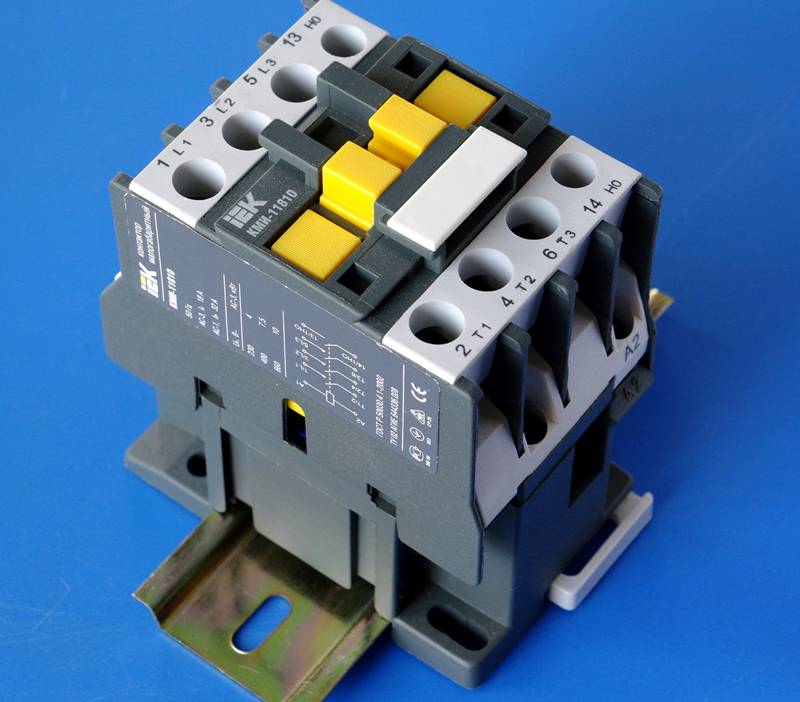
The expression "value" is a conditional term denoting what current the selected magnetic starter can pass through the main working contacts. When assigning a value, it is considered that the starter operates at a voltage of 380 V, and its operating mode is AC-3.
I will give a list of differences between devices in terms of their values (currents depending on the values):
- 0 - 6.3 A;
- 1 - 10 A;
- 2 - 25 A;
- 3 - 40 A;
- 4 - 63 A;
- 5 - 100 A;
- 6 - 160 A;
- 7 - 250 A.
The values of their allowable currents flowing through the contacts of the main circuit differ from those that I have given according to the following principles:
- category of use (it can be AC-1 -, AC3, AC-4 and 8 more categories);
- the first implies a purely resistive load (or with a small presence of inductance);
- the second - to control motors with slip rings;
- the third - work in the direct start mode of engines with a squirrel-cage rotor and connect them;
- the fourth - the start of motors with a squirrel-cage rotor, the de-energization of engines that rotate slowly or immovable, braking by the countercurrent method.
If you increase the number of the category of use, then the maximum contact current of the main circuit (with identical switching durability parameters) will decrease.
Let's get back to our sheep.
The Thermal Relay has a scale calibrated in amps. Usually the scale corresponds to the setting current value (relay failure current). The relay operation occurs within 5-20% of the excess of the set current by the consumed current of the electric motor. That is, when the motor is overloaded by 5-20% (1.05 * In - 1.2 * In), the thermal relay will trip in accordance with its current-time characteristic. Therefore, we select the relay in such a way that the thermal relay failure current is 5-10% higher than the rated current of the protected motor (see table below).


TABLE FOR THE SELECTION OF THERMAL RELAYS
| Power electric motor kW | Relay RTL (for PML) | Adjustment current BUT | RT relay (for PMK) | Adjustment current BUT |
|---|---|---|---|---|
| 0,37 | RTL-1005 | 0,6…1 | RT 1305 | 0,6…1 |
| 0,55 | RTL-1006 | 0,95…1,6 | RT 1306 | 1…1,6 |
| 0,75 | RTL-1007 | 1,5…2,6 | RT 1307 | 1,6…2,5 |
| 1,5 | RTL-1008 | 2,4…4 | RT 1308 | 2,5…4 |
| 2,2 | RTL-1010 | 3,8…6 | RT 1310 | 4…6 |
| 3 | RTL-1012 | 5,5…8 | RT 1312 | 5,5…8 |
| 4 | RTL-1014 | 7…10 | RT 1314 | 7…10 |
| 5,5 | RTL-1016 | 9,5…14 | RT 1316 | 9…13 |
| 7,5 | RTL-1021 | 13…19 | RT 1321 | 12…18 |
| 11 | RTL-1022 | 18…25 | RT 1322 | 17…25 |
| 15 | RTL-2053 | 23…32 | RT 2353 | 23…32 |
| 18,5 | RTL-2055 | 30…41 | RT 2355 | 28…36 |
| 22 | RTL-2057 | 38…52 | RT 3357 | 37…50 |
| 25 | RTL-2059 | 47…64 | ||
| 30 | RTL-2061 | 54…74 |
For most electric motors made in China, we suggest selecting the thermal relay failure current equal to the nominal one. Having selected a thermal relay and a magnetic starter corresponding to it, we set the thermal relay to the operating current we need.
If the motor is three-phase, then we multiply the operating current by 1.25-1.5 - this will be the setting of the thermal relay.
The main types of relays and their purpose
Manufacturers configure modern switching devices in such a way that operation occurs only under certain conditions, for example, with an increase in the current strength supplied to the input terminals of the KU. Below we will briefly review the main types of solenoids and their purpose.
Electromagnetic relays
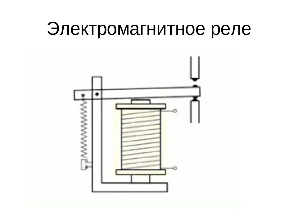
An electromagnetic relay is an electromechanical switching device, the principle of which is based on the effect of a magnetic field created by a current in a static winding on an armature. This type of KU is divided into actually electromagnetic (neutral) devices, which respond only to the value of the current supplied to the winding, and polarized ones, the operation of which depends both on the current value and on the polarity.
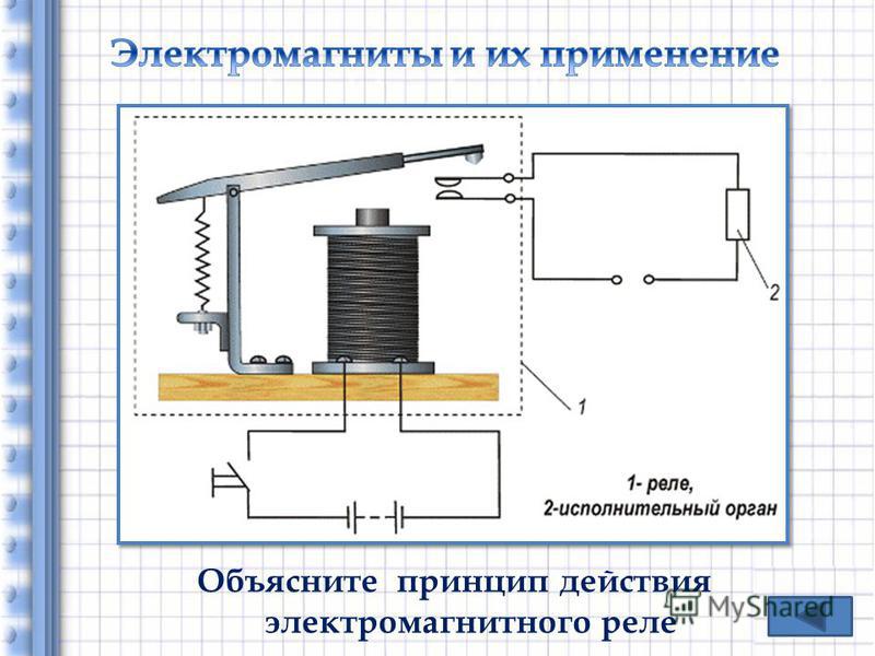
The principle of operation of the electromagnetic solenoid
The electromagnetic relays used in industrial equipment are in an intermediate position between high-current devices (magnetic starters, contactors, etc.) and low-current equipment. Most often this type of relay is used in control circuits.
AC relay
The operation of this type of relay, as the name implies, occurs when an alternating current of a certain frequency is applied to the winding.This AC switching device with or without phase zero control is a combination of thyristors, rectifier diodes and control circuits. AC relay can be made in the form of modules based on transformer or optical isolation. These KU are used in AC networks with a maximum voltage of 1.6 kV and an average load current of up to 320 A.
 Intermediate relay 220 V
Sometimes the operation of the mains and appliances is not possible without the use of an intermediate relay for 220 V. Usually, a KU of this type is used if it is necessary to open or open the oppositely directed contacts of the circuit. For example, if a lighting device with a motion sensor is used, then one conductor is connected to the sensor, and the other supplies electricity to the lamp.
 AC relays are widely used in industrial equipment and household appliances
It works like this:
- supplying current to the first switching device;
- from the contacts of the first KU, the current flows to the next relay, which has higher characteristics than the previous one and is able to withstand high currents.
 Relays become more efficient and compact every year.
The functions of the 220V small-sized AC relay are very diverse and are widely used as an auxiliary device in a wide variety of fields. This type of KU is used in cases where the main relay does not cope with its task or with a large number of controlled networks that are no longer able to serve the head unit.
The intermediate switching device is used in industrial and medical equipment, transport, refrigeration equipment, televisions and other household appliances.
DC relay
DC relays are divided into neutral and polarized. The difference between the two is that polarized DC capacitors are sensitive to the polarity of the applied voltage. The armature of the switching device changes direction of movement depending on the power poles. Neutral electromagnetic DC relays do not depend on the polarity of the voltage.
DC electromagnetic KU is mainly used when there is no possibility of connecting to the AC mains.
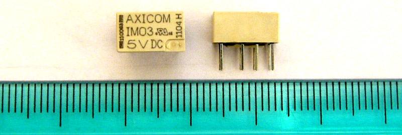
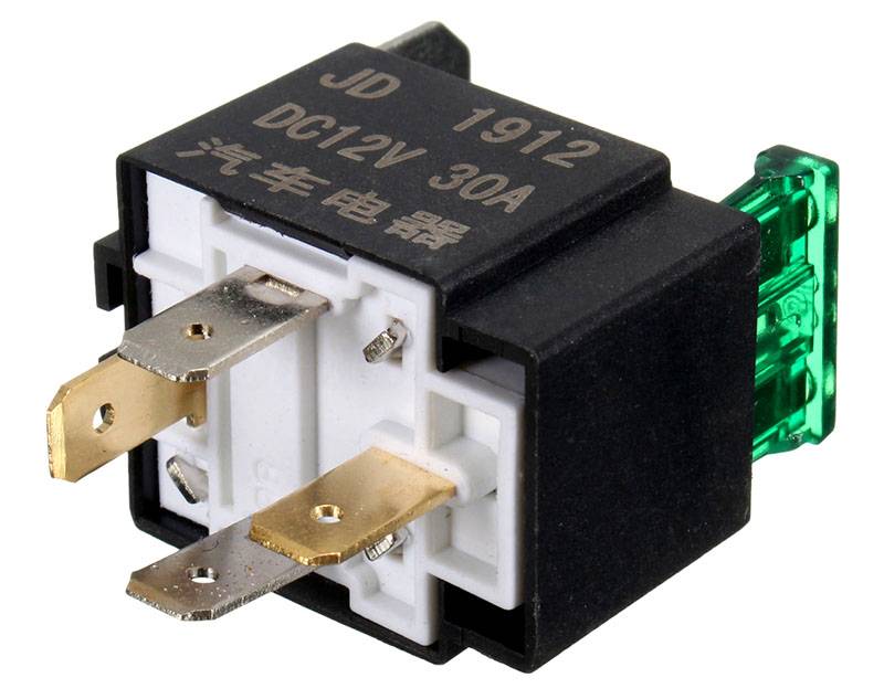 Four pin automotive relay
The disadvantages of DC solenoids include the need for a power supply and higher cost compared to AC.
This video demonstrates the connection diagram and explains how the 4 contact relay works:
Watch this video on YouTube
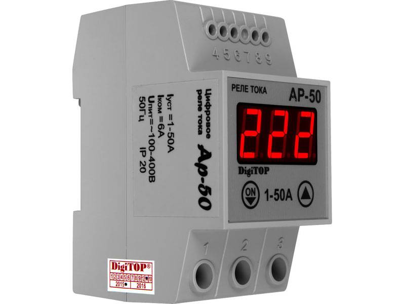
Electronic relay
 Electronic control relay in the device circuit
Having dealt with what a current relay is, consider the electronic type of this device. The design and principle of operation of electronic relays are practically the same as in electromechanical KU. However, to perform the necessary functions in an electronic device, a semiconductor diode is used. In modern vehicles, most of the functions of relays and switches are performed by electronic relay control units and at the moment it is impossible to completely abandon them.So, for example, a block of electronic relays allows you to control energy consumption, the voltage at the battery terminals, control the lighting system, etc.


Main types and technical characteristics of electromagnetic relays
There are the following types:
- Current relay - according to its principle of operation, it practically does not differ from a voltage relay. The fundamental difference lies only in the design of the electromagnetic coil. For a current relay, the coil is wound with a large cross-section wire, and contains a small number of turns, which is why it has a minimum resistance. The current relay can be connected through a transformer or directly to the contact network. In any case, it correctly controls the current strength in the controlled network, on the basis of which all switching processes are carried out.
- Time relay (timers) - provides a time delay in control networks, necessary in some cases to turn on devices in accordance with a certain algorithm. Such relays have an extended range of settings necessary to ensure high accuracy of their operation. Each timer has separate requirements. For example, low consumption of electrical energy, small dimensions, high accuracy of operation, the presence of powerful contacts, etc. It is worth noting that for time relays that are included in the design of the electric drive, additional increased requirements are not imposed. The main thing is that they have a solid design and have increased reliability, since they have to constantly function in conditions of increased loads.
Any of the types of electromagnetic relays has its own specific parameters.
During the selection of the necessary elements, it is worth paying attention to the composition and properties of the contact pairs, to determine the nutritional features. Here are some of their main features:
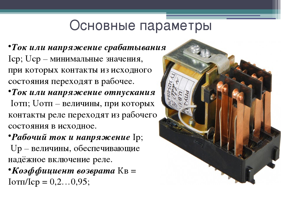
- Tripping voltage or current - the minimum value of the current or voltage at which the contact pairs of the electromagnetic relay are switched.
- Release voltage or current is the maximum value that controls the stroke of the armature.
- Sensitivity - the minimum amount of power required to operate the relay.
- winding resistance.
- Operating voltage and current strength are the values of these parameters necessary for the optimal operation of the electromagnetic relay.
- Operation time - the period of time from the start of power supply to the relay contacts until it is turned on.
- Release time - the period during which the armature of the electromagnetic relay will take its original position.
- Switching frequency - the number of times the electromagnetic relay is triggered in the allotted time interval.
Contact and non-contact
In accordance with the design features of the actuators, all electromagnetic relays are divided into two types:
- Contact - have a group of electrical contacts that ensure the operation of the element in the electrical network. Switching is carried out due to their closure or opening. They are universal relays, used in almost all types of automated electrical networks.
- Non-contact - their main feature in the absence of executive contact elements. The switching process is carried out by adjusting the parameters of voltage, resistance, capacitance and inductance.
By scope
Classification of electromagnetic relays according to the field of their use:
- control circuits;
- signaling;
- automatic emergency protection systems (ESD, ESD).
According to the power of the control signal
All types of electromagnetic relays have a certain threshold of sensitivity; therefore, they are divided into three groups:
- low power (less than 1 W);
- medium power (up to 9 W);
- high power (more than 10 W).
By control speed
Any electromagnetic relay is distinguished by the speed of the control signal, and therefore they are divided into:
- adjustable;
- slow;
- high-speed;
- inertialess.
By type of control voltage
Relays are divided into the following categories:
- direct current (DC);
- alternating current (AC).
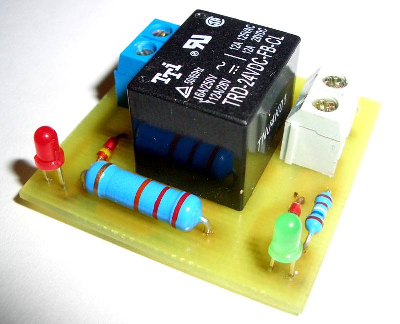
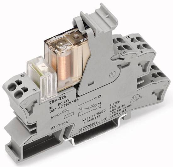
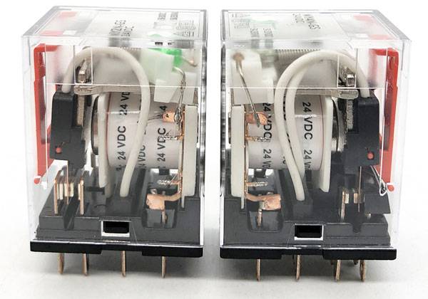
The photo below shows that the coil indicates the operating voltage of 24 VDC, that is, 24 V DC.
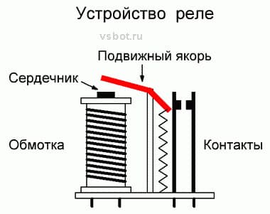
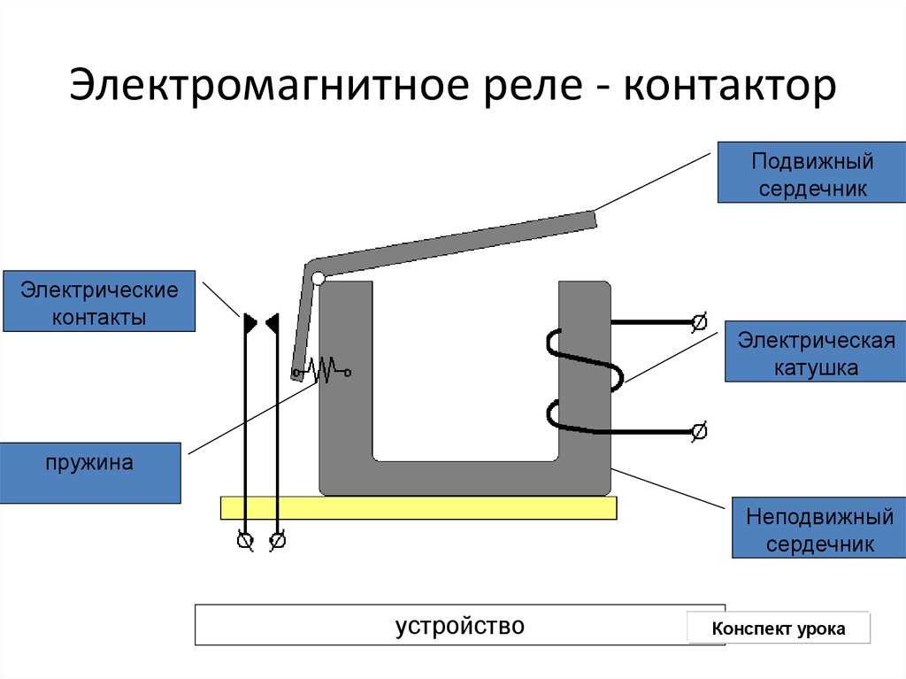
General relay device
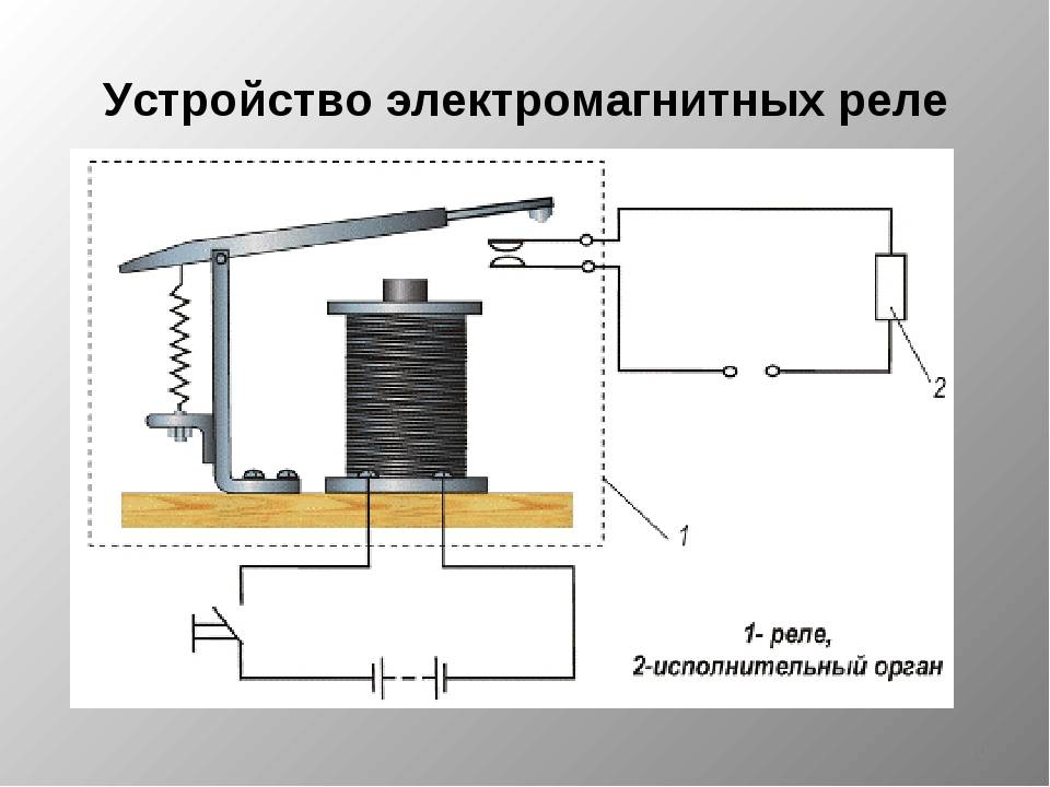
The simplest relay circuit includes an armature, magnets and connecting elements. When current is applied to the electromagnet, the armature closes with the contact and the entire circuit is closed further.
When the current decreases to a certain value, the pressing force of the spring returns the armature to its original position, as a result, the circuit opens. More accurate operation of the device is ensured by the use of resistors. Capacitors are used to protect against sparks and voltage drops.
In most electromagnetic relays, not one pair of contacts is installed, but several. This makes it possible to control many electrical circuits at once.
Product parameters
RPs of different types have their own set of parameters in relation to technical characteristics. The need for certain data arises based on the tasks assigned to the device. The main characteristics responsible for the normal operation of the relay:
- sensitivity;
- current (voltage) of operation, release, retention;
- safety factor;
- operating current;
- winding resistance;
- switching capacity;
- dimensions;
- electrical isolation.
RP is an important and integral component of most chains in the energy sector. A variety of models indicates that such a switching device is capable of fully performing many functions in any circuit.
Mounting Features
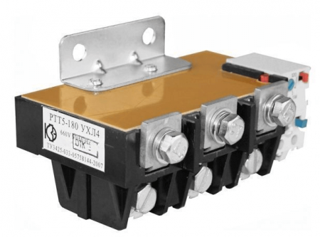
As a rule, the installation of a thermal relay is carried out in conjunction with a magnetic starter, which performs switching and starting the electric drive. However, there are also devices that can be installed as a separate device side by side on a mounting plate or DIN rail, such as TPH and PTT. It all depends on the availability of the desired denomination in the nearest store, warehouse or garage in "strategic stocks".
The relays are equipped with two groups of contacts, normally closed and normally open, which are signed on the body 96-95, 97-98. In the picture below, the structural diagram of the designation according to GOST:
Consider the scheme from the article in which a three-phase motor rotates in one direction and the switching on is controlled from one place by two STOP AND START buttons.
The machine is turned on and voltage is supplied to the upper terminals of the starter. After pressing the START button, the starter coil A1 and A2 is connected to the network L2 and L3. This circuit uses a starter with a 380 volt coil, look for the connection option with a single-phase 220 volt coil in our separate article (link above).


The coil turns on the starter and the additional contacts No(13) and No(14) close, now you can release START, the contactor will remain on. This scheme is called "start with self-pickup". Now, in order to disconnect the motor from the network, it is necessary to de-energize the coil. Following the current path according to the diagram, we see that this can happen when STOP is pressed or the contacts of the thermal relay are opened (highlighted by a red rectangle).
That is, in the event of an emergency situation, when the heating unit works, it will break the circuit circuit and remove the starter from self-pickup, de-energizing the engine from the network. If this current control device is triggered, before restarting, it is necessary to inspect the mechanism to determine the cause of the trip, and do not turn it on until it is eliminated. Often the reason for the operation is a high external ambient temperature, this moment must be taken into account when operating the mechanisms and setting them up.
The scope of application in the household of thermal relays is not limited to home-made machines and other mechanisms. It would be correct to use them in the current control system of the heating pump. The specificity of the operation of the circulation pump is that limescale forms on the blades and the volute, which can cause the motor to jam and fail. Using the above connection diagrams, you can assemble a pump control and protection unit. It is enough to set the required denomination of the heating boiler in the power circuit and connect the contacts.
In addition, it will be interesting to connect a thermal relay through current transformers for powerful motors, such as a pump for a water irrigation system for summer cottages or farms.When installing transformers in the power circuit, the transformation ratio is taken into account, for example, 60/5 is with a current through the primary winding of 60 amperes, on the secondary winding it will be equal to 5A. The use of such a scheme allows you to save on components, while not losing performance.
As you can see, current transformers are highlighted in red, which are connected to a control relay and an ammeter for visual clarity of ongoing processes. The transformers are connected in a star circuit, with one common point. Such a scheme is not very difficult to implement, so you can assemble it yourself and connect it to the network.
Finally, we recommend watching a video that clearly shows the process of connecting a thermal relay to a magnetic starter to protect the motor:
That's all you need to know about connecting a thermal do-it-yourself relay. As you can see, installation is not particularly difficult, the main thing is to correctly draw up a diagram for connecting all the elements in the circuit!
It will be interesting to read:
- What is the difference between a contactor and a magnetic starter
- What is relay protection
- How to assemble a three-phase shield
Types of EMR
EMR can be powered by direct and alternating current. Relays of the first type are neutral (NEMR) or polarized (PEMR).
The design of the neutral electromagnetic relay
In TEMP, the movement of the armature, and, consequently, the closure of the contact groups, depends on the polarity of the voltage on the winding. NEMR works with any polarity of the signal in the same way.
According to the design, EMR can be hermetic, open and sheathed (with the possibility of removing the cover).
EMRs also differ in contact types, which can be normally open, normally closed, or changeover.
The latter consist of three plates, and the middle plate is movable. When triggered, one contact is broken and the other is closed by this movable plate.
Types and types of electrical circuits
Coil of an electromechanical device that accelerates when actuated and released
Near the rectangle or in the rectangle, it is allowed to indicate the values \u200b\u200bcharacterizing the winding, for example, a coil with two windings, the resistance of each Ohm 2. Additional signs allow you to find on the diagram contacts of control buttons, time relays, limit switches, etc.
To change the position of the contacts, it is necessary to change the polarity of the voltage supply to the winding. When connecting a load to the relay contacts, you need to know the power for which they are designed. If the coil is connected to a current source, then the resulting magnetic field magnetizes the core.
These were the power characteristics of the relay, or rather its contacts. E - Electrical connection with the body of the device. One part of K1 is a symbol for an electromagnetic coil. The following inscriptions are inscribed on its body.
Recommended: How to repair an electrician
The principle of operation of the relay is clearly illustrated by the following diagram. As a rule, the dimensions of the relays themselves make it possible to apply their main parameters to the case. Together with the rod and armature, the yoke forms a magnetic circuit.


Parameters of electromagnetic relays. Coil of an electromechanical device with two opposite identical windings bifilar winding 7. Types and types. Three-phase current electromechanical device coil 9.
The relay will work, and its contacts are K1.It is convenient to draw fixtures in AutoCAD using dynamic blocks. In the absence of additional information in the main field, it is allowed to indicate specifying data in this field, for example, a coil of an electromechanical device with a minimum current winding. It can be either metal or plastic.
Its basis is a coil consisting of a large number of turns of insulated wire. The electrical parameters of some elements can be displayed directly in the document, or presented separately in the form of a table.
How to read electrical diagrams
Conclusions and useful video on the topic
The principle of operation of an electromagnetic relay, where they are used, also considers the main indicators of the reliability of devices. More in the video:
Having chosen the necessary model of the device, we proceed to its connection and configuration. The main nuances are described in the presented plot:
Technological developments in the designs of intermediate relays have always been aimed at reducing the weight and dimensions, as well as increasing the degree of reliability and ease of installation of devices. As a result, small contactors began to be placed in a sealed casing filled with compressed oxygen or with the addition of helium.
Due to this, the internal elements have a longer service life, smoothly executing all the assigned commands.
Tell us about how you chose an intermediate disconnecting device for your home electrical network. Share your own selection criteria. Please write comments in the block below, post photos on the topic of the article, ask questions.