- The principle of operation of drive mechanisms
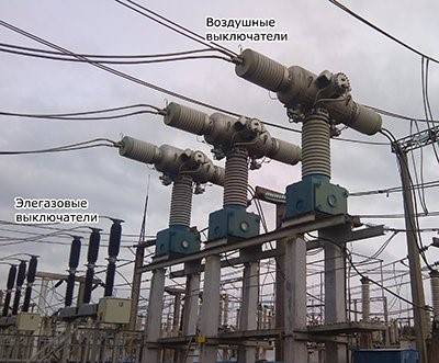
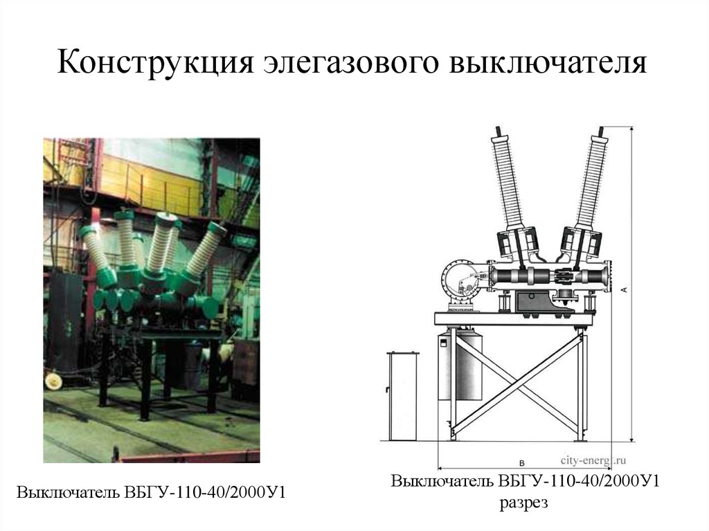
- Construction of SF6 circuit breakers
- Operating principle
- Features of maintenance and operation
- Advantages and disadvantages
- 2.4.5 SF6 and the environment
- Operating principle
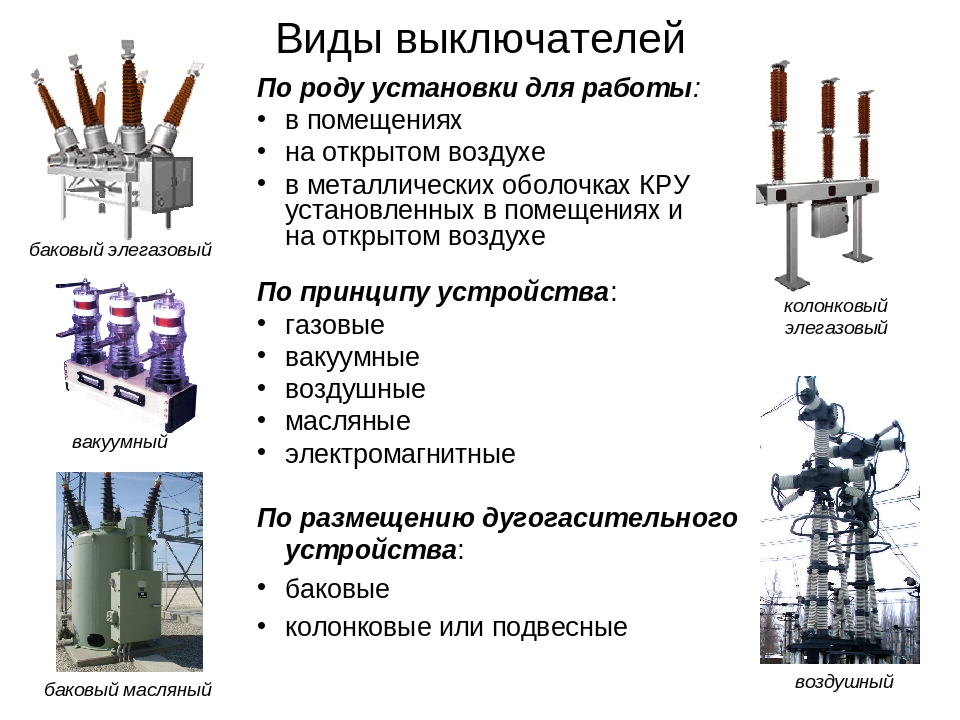
- Classification and types of air circuit breakers
- By appointment
- By design
- Morally and physically obsolete circuit breakers that are in operation create many problems.
- Application area
- Principle of operation and scope
- The device and design of the air circuit breaker
The principle of operation of drive mechanisms
The pneumatic actuator works by the pressure of compressed air moving from one chamber to another, driving pistons, which ultimately apply pressure to the isolation rod. The initial command impulse is transmitted to the electromagnets (switching on or off), which, by drawing in the cores, open the access of compressed air to the piston chambers.
The hydraulic drive works due to the fluid pressure created by the low power pumping station. The control takes place by means of a hydraulic signal (pressure increase). Thus, a series of valves are actuated, which transmit movement to the insulating rod, which in turn actuates the moving contact of the SF6 circuit breaker.The reverse motion of the mechanism is carried out by reducing the fluid pressure.
The spring drive has the simplest operation scheme, which is based on the properties of the spring. The operation of such a device is based purely on mechanical components. Powerful spring fixed with certain parameters compression. With the help of the control handle, the fixation is removed and the spring, unclenching, sets the rod in motion. Some mechanisms are supplemented with hydraulic systems for more reliable fixation.
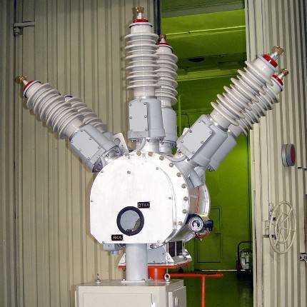
Construction of SF6 circuit breakers
The arc-extinguishing ability of SF6 gas is most effective at a high speed of its jet relative to the burning arc. The following executions of remote control with SF6 gas are possible:
1) with autopneumatic blowing. The pressure drop required for blowing is generated by the drive energy;
2) with the cooling of the arc by SF6 during its movement, caused by the interaction of the current with the magnetic field.
3) with arc extinguishing due to gas flow from the high pressure tank to the low pressure tank (double pressure switches).
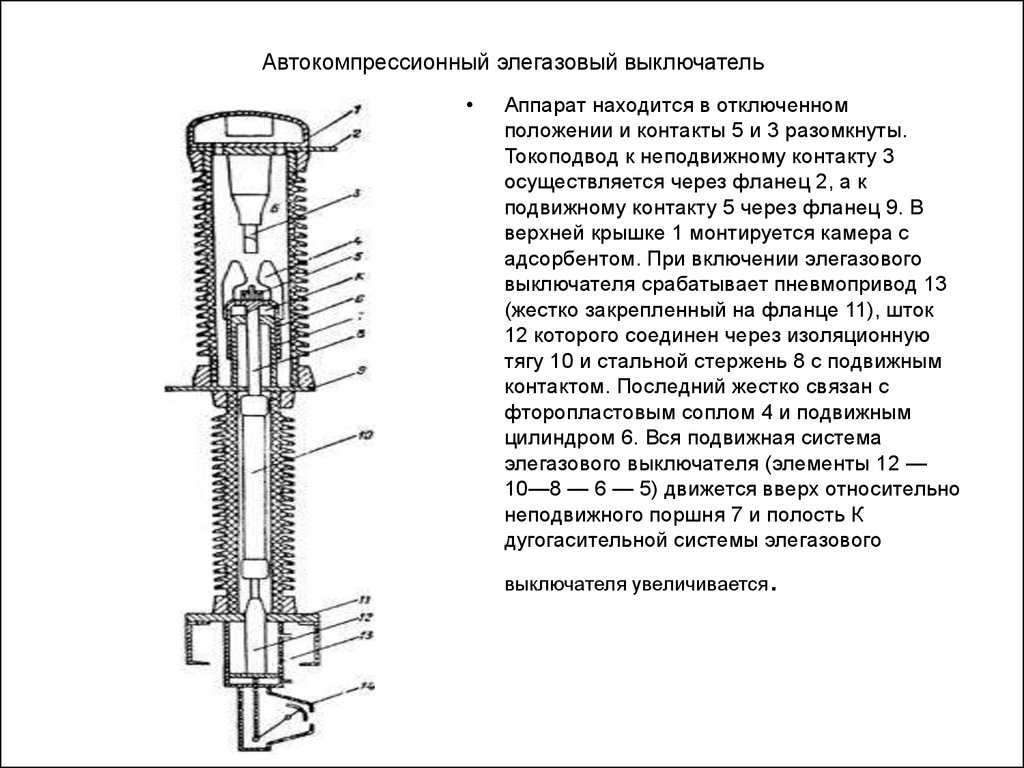
At present, the first method is widely used. An arc quenching device with autopneumatic forced blast is shown in fig. 22. It is located in a sealed tank with an SF6 gas pressure of 0.2–0.28 MPa. In this case, it is possible to obtain the necessary electrical strength of the internal insulation. When disconnected, an arc occurs between the fixed 1 and moving 2 contacts. Together with the movable contact 2, when disconnected, the PTFE nozzle 3, the partition 5 and the cylinder 6 move. Since the piston 4 is stationary, the SF6 gas is compressed and its flow, passing through the nozzle, washes the arc longitudinally and ensures its effective extinguishing.
Rice. 22.Scheme of the arc extinguishing device of the SF6 circuit breaker with autopneumatic blast
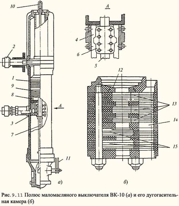
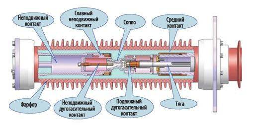
Rice. 23. Arcing chamber of the SF6 circuit breaker
For switchgear, a SF6 circuit breaker with a rated voltage of 110 and 220 kV, a rated current of 2 kA and a rated breaking current of 40 kA has been developed. Turn-off time 0.065, turn-on time 0.08 s, SF6 nominal pressure 0.55 MPa, pneumatic drive with air pressure 2 MPa.
220 kV SF6 circuit breaker remote control chamber with two breaks per pole shown in fig. 23. When the circuit breaker is turned on, cylinder 1, together with the main 2 and arcing 3 contacts associated with it, moves to the right. In this case, pipe 2 enters socket 5, and socket 3 is connected to contact 4. Fluoroplastic nozzle 6 also moves to the right and moves onto hollow tubular contact 4. SF6 gas is sucked into cavity A, and SF6 gas is displaced from cavity B.
When turned off, cylinder 1 and pipe 7 move to the left. First, the main contacts (2, 5) diverge, then the arcing contacts (3, 4). At the moment of opening contacts 3 and 4, an arc occurs, which is subjected to gas blowing. The piston 10 remains stationary. In area A, a compressed gas is formed, and in area B, a rarefied one. As a result, the gas flows from region A through the hollow contact 7 to region B through holes 8 and 9 under the action of the pressure difference pl—(—Pb). A large pressure drop makes it possible to obtain the necessary (critical) arc blowing speed. Under severe shutdown conditions (non-remote short circuit), the arc is also extinguished due to its cooling in nozzle 6 after it leaves contact 4.
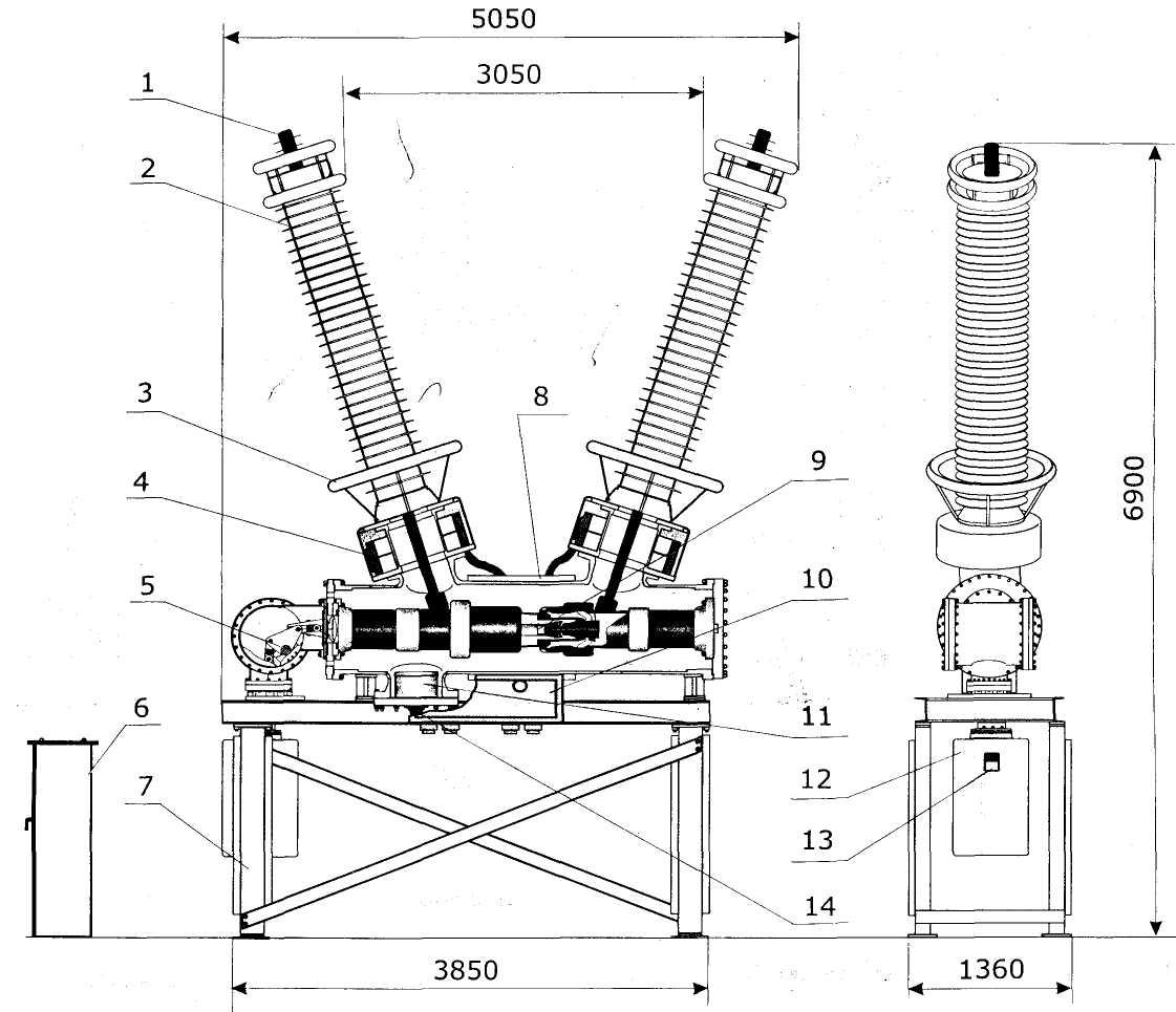
Rice. 24. The device of the SF6 circuit breaker for voltage 220 kV
On fig.24 shows the basic arrangement of a SF6 circuit breaker for KRUE-220 for a voltage of 220 kV. The fixed contact of the circuit breaker 1 is attached to the tank of the circuit breaker on a cast insulator 2. The circuit breaker has two PS 3 and 4 connected in series through the housing 11. Uniform voltage distribution over the PS is ensured by ceramic capacitors 6. To eliminate corona, the PS is covered with screens 5. Cylinders 3 and 4 are driven in the movement of the insulating rod 8 Through the lever mechanism 7. Switching on and off of the circuit breaker is performed by a pneumatic drive. The circuit breaker is filled with SF6 at a pressure of 0.55 MPa. The fixed contacts of the circuit breaker 1 are led out of the tank through a sealed insulator 9 and 10 - SF6-SF6 gas, which means a transition from the circuit breaker cavity filled with SF6 gas to the cavity of the complete switchgear, also filled with SF6 SF6 gas (PRUE). Here 9 is an insulating partition, 10 is a plug-in socket type contact. Such an insulator makes it possible to store SF6 gas in the circuit breaker when it is disconnected from the switchgear.
The described SF6 circuit breaker has high technical performance and allows a 20-fold short-circuit current interruption of a limit value of 40 kA without revisions. The leakage of SF6 gas from the tank does not exceed 1% per year. The service life of the circuit breaker before overhaul is 10 years. DD with a rated voltage of 220 kV per break and a tripping current of 40 kA at a high voltage recovery rate have been developed. Prototypes of SF6 circuit breakers allow a breaking current of up to 100 kA at a break voltage of 245 kV and a current of 40 kA at a break voltage of up to 362 kV. SF6 circuit breakers are the most promising for voltages above 35 kV and can be created on voltage 800 kV and above.
-
Back
-
Forward
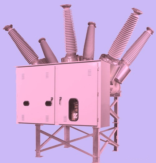
Operating principle
The principle of operation of air circuit breakers is based on the extinguishing of an electric arc that appears when the load is broken. This process can occur in two types of air movement:
- Longitudinal;
- Transverse.
An air circuit breaker may have several contact breaks, and this depends on the voltage rating for which it is rated. To facilitate the extinguishing of particularly large types of arcs, a shunt resistor is connected to the arcing contacts. Automatic air circuit breakers operating on the principle of arc extinguishing in conventional chambers do not have such elements without the presence of compressed air. Their arc extinguishing chamber consists of partitions that break the arc into small parts, and therefore it does not flare up and quickly goes out. In this article, we will talk more about the operation of high-voltage (above 1000 Volts) switches that are not equipped with built-in, but have control in the circuit of which relay protections are introduced.
The principle of operation of a high-voltage circuit breaker with compressed air differs from each other in design features, and in particular, with and without a separator.
In switches equipped with separators, the power contacts are connected to special pistons and form one contact-piston mechanism. The separator is connected in series to the arc extinguishing contacts. That is, a separator with arcing contacts forms one pole of the circuit breaker. In the closed position, both the arcing contacts and the separator are in the same closed state. When a shutdown signal is given, a mechanical pneumatic valve is activated, which in turn opens the pneumatic actuator, while the air from the expander acts on the arc extinguishing contacts.The expander, by the way, is also called a receiver by experts. In this case, the power contacts open, and the resulting arc is extinguished by a stream of compressed air. After that, the separator itself is turned off, breaking the current that remains. The air supply must be precisely adjusted so that it is enough for confident extinguishing of the arc. After the air supply is interrupted, the arcing contacts take on the on position, and the circuit is interrupted only by an open circuit breaker. Therefore, when working on electrical installations that are powered by such switches, it is imperative to open the disconnectors for safe work. One shutdown of the pneumatic switch is not enough! Most often, in circuits up to 35 kV, a design with open separators is used, and if the voltage at which the switch operates is higher, then the separators are already made in the form of special air-filled chambers. Switches with a separator, for example, were produced in the Soviet Union under the brand name VVG-20.


If the high-voltage air switch does not have a separator, then its arcing contacts also play the role of breaking the circuit and extinguishing the resulting arc. The drive in them is separated from the medium in which the damping takes place, and the contacts can have one or even two stages of operation.
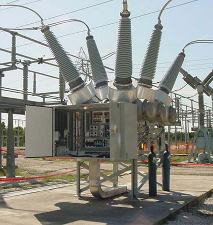
Features of maintenance and operation
During the operation of such switching devices on outdoor switchgear (open switchgears), it must be taken into account that condensate can accumulate in the switch cabinets, which leads to corrosion of the mechanism systems, as well as secondary control and signaling circuits. To do this, the manufacturer provides heating resistors inside the cabinets that work constantly.
All actions to turn on or turn off the devices are possible only if the gas pressure is not less than the permissible one, if this is neglected, then there is a high probability of damage and failure of a relatively expensive switch. For these purposes, a minimum pressure alarm must be set up, as well as blocking the control circuits.
If the personnel noticed that the pressure has dropped, the device must be taken out for repair and the search for the reasons for the decrease in this vital indicator for it should be started. Naturally, its withdrawal from work must be carried out with all the necessary safety requirements for this electrical installation and set out in local instructions.
To control the pressure, there must be a working pressure gauge, and after eliminating the gas leak, it is worth supplementing it through a special connection, which is located inside the drive mechanism.
Inspection of SF6 circuit breakers is carried out daily, as well as once every two weeks at night
In wet damp weather, you need to pay attention to the occurrence of electrical corona. If the value of the disconnected current was the maximum permissible (during short circuits), then quality maintenance should be ensured
The number of shutdowns, both planned and emergency, is recorded in logs specially allocated for these needs.
Despite the existing shortcomings, the SF6 circuit breaker has its strengths, therefore it is a worthy replacement not only for oil, but also for high voltage air circuit breakers.
Advantages and disadvantages
There are few advantages of such outdated devices, here are the main ones:
- Due to the long-standing use, there is a lot of experience in both operation and repair;
- Unlike other more modern counterparts (especially SF6), these switches can be repaired.
Among the shortcomings, I would like to highlight the following:
- Availability of additional pneumatic equipment or compressors for operation;
- Increased noise during shutdown, especially during emergency short circuit modes;
- Large non-modern dimensions, which causes an increase in the territory allocated for outdoor switchgear;
- They are afraid of humid air and dust. Therefore, additional measures are taken for air systems, equipment is installed aimed at reducing these harmful factors.
2.4.5 SF6 and the environment
Substances that pollute the atmosphere resulting from human activities are divided into two categories according to the impact they have:
— stratospheric ozone depletion (holes in the ozone layer);
- global warming (greenhouse effect).
SF6 has little effect on stratospheric ozone depletion, since it does not contain chlorine, which is the main reactant in ozone catalysis, nor on the greenhouse effect, since its quantities present in the atmosphere are negligible (IEC 1634 (1995)).
The use of SF6 gas in switchgear for all operating conditions has brought benefits in terms of performance, size, weight, overall cost and reliability. The cost of purchase and operation, which includes maintenance costs, can be significantly lower than the cost of legacy switching equipment.
Many years of operating experience shows that SF6 does not pose any danger to the operating personnel or the environment, provided that the elementary rules for handling and operating gas-insulated equipment are observed.


-
Back
-
Forward
Operating principle
The switch is based on the principle of extinguishing an electric arc by a high-speed flow of a compressed air mixture supplied to the blast channels. Under the influence of the air flow, the discharge column is stretched and directed to the blast channels, where it is finally extinguished.
The designs of arc chutes differ both in the mutual arrangement of the air ducts and in the breaking contacts. On this basis, the following blast schemes:
- Longitudinal blowing through a metal channel.
- Longitudinal blowing through the insulating channel.
- Double-sided symmetrical purge.
- Bilateral asymmetric.
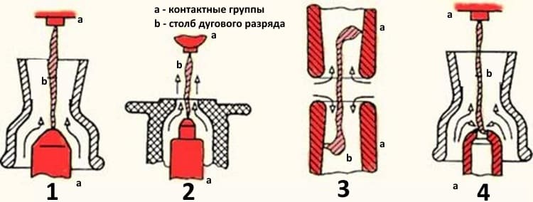
Schemes of blowing Of the presented options, the last one is the most effective.
Classification and types of air circuit breakers
Power switches, including air ones, are primarily classified according to the type of construction and purpose, after which technical characteristics are already considered. Let's start with a more priority classification criterion.
By appointment
Depending on the purpose, air switches are divided into the following types:
- Network group, it includes electromechanical devices, with a rated voltage starting from 6.0 kV. They can be used both for operational switching of circuits and emergency shutdown, for example, in case of short circuit.
- generator group. It includes electric devices designed for 6.0-20.0 kV. These devices can switch the circuit, both under normal conditions and in the event of a short circuit or the presence of inrush currents.
- Category for work with energy-intensive consumers (arc, ore-thermal, steel-smelting furnaces, etc.).
- Special Purpose Group. It includes the following subspecies:
- Air switches of ultra-high voltage category, used to connect shunt reactors to power lines if an overvoltage occurs in the line.
- Circuit breakers with shock generators (used in bench tests), designed for switching in normal operation and in emergency situations.
- Devices in circuits 110.0-500.0 kV, providing passage, both under normal operating conditions, and for a certain time during short circuit.
- Air switches included in the switchgear kit.
By design
The design features of the switches determine their type of installation. Depending on this, the following types of devices are distinguished:
- Included in the kit for the switchgear (built-in).
- Roll-outs from switchgear cells equipped with special devices are of the roll-out type.
Withdrawable air circuit breaker Metasol
- Wall execution. Devices installed on walls in a closed-type switchgear.
- Suspended and supporting (differ in the type of insulation to the "ground").
Morally and physically obsolete circuit breakers that are in operation create many problems.
According to RAO UES, 15% of all high voltage circuit breakers do not meet the operating conditions; wear of substation equipment exceeds 50%. More than a third of 330-750 kV air circuit breakers, which form the basis of the switching equipment of intersystem power networks, has a service life of more than 20 or even 30 years. A similar situation is with switching equipment for a voltage of 110-220 kV.
Outdated circuit breakers and their support systems require high maintenance costs.
Until 2010, no alternatives to SF6 and vacuum circuit breakers can be seen on the world market.Therefore, work continues to improve them.
A combination of the autopneumatic method of extinguishing and the method of auto-generation of pressure in SF6 circuit breakers, which has become widespread in recent years, is used. This reduces the energy consumption of the drive and makes it possible to use an economical and reliable spring drive for SF6 circuit breakers with a voltage of 245 kV and above.


Increasing the efficiency of arc extinguishing makes it possible to increase the voltage per break of the circuit breaker up to 360-550 kV.
Work is underway to further improve the contact systems of the VDC, to search for the optimal distribution of the magnetic field for effective damping of the vacuum arc and reducing the diameter of the chambers. Work continues on the creation of VDC for a voltage of more than 35 kV (110 kV and above) for high voltage vacuum circuit breakers.
Vacuum equipment is beginning to be used at low voltage (1140 V and below), and not only in the form of contactors, but also switches and control devices.
Work is underway to replace SF6 with a mixture of it with other gases, as well as to use other gases.
The level of development of SF6 and vacuum equipment basically satisfies the requirements of the consumer.
Today's supply on the Russian foreign market of gas-insulated equipment significantly exceeds the volume of sales of domestic devices. It is becoming increasingly difficult for Russian manufacturers to compete with foreign ones due to technological backwardness and lack of funds for technical re-equipment.
2814
Bookmarks
Latest publications
EKF company received a patent for SMK-222 connecting feed-through terminals
November 27 at 17:11
33
New range of frequency converters Vector80 EKF Basic
November 27 at 17:10
35
KRUG improves the energy efficiency of pumping station No. 4 of the Saratov heating networks
November 26 at 18:39
74
Atos provides Norilsk Nickel with BullSequana S platform for SAP implementation
November 26 at 14:48
79
National Research University "MPEI" discussed the problems of training personnel for the electric and thermal power industry with representatives of the state and business
November 24 at 21:07
107
National Research University "MPEI" spoke about the creation of the University 3.0. at the UASR Presidential Forum
November 23 at 22:35
62
KTPM 35 kV on the street. Lev Tolstoy
November 23 at 12:25
197
Convenient dielectric tool kits for installers from EKF
November 22 at 23:34
197
New packaging size for flexible corrugated HDPE pipes from EKF
November 22 at 23:33
190
Bracket from EKF with a support for mounting trays on the walls
November 22 at 23:31
257
Most interesting publications
The new gas turbine CHPP in Kasimov will provide more than 18 MW of power to the energy system of the Ryazan region
June 4, 2012 at 11:00 am
147466
SF6 circuit breaker type VGB-35, VGBE-35, VGBEP-35
July 12, 2011 at 08:56
31684
Load switches for voltage 6, 10 kV
November 28, 2011 at 10:00 am
19520
SF6 tank circuit breakers type VEB-110II
July 21, 2011 at 10:00 am
13899
Correct disposal of batteries
November 14, 2012 at 10:00 am
13250
Signs of a malfunction in the operation of power transformers during operation
February 29, 2012 at 10:00 am
12581
Switchgear 6(10) kV with microprocessor terminals BMRZ-100
August 16, 2012 at 16:00
12015
We draw up the "Statement of operational documents"
May 24, 2017 at 10:00 am
11856
Problems in the system of concepts. Lack of logic
December 25, 2012 at 10:00 am
11049
Calculation of networks by voltage losses
February 27, 2013 at 10:00 am
9150
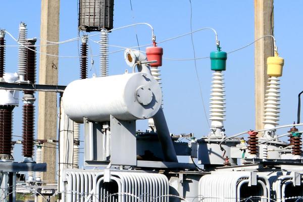
Application area
The SF6 voltage transformer is used in various electrical substations. The device is capable of transmitting a signal to measuring instruments, protective components of switchgear. SF6 transformers are connected to a three-phase (industrial) network. Their task is to transform alternating current 50 Hz. Installation is permitted in medium and moderately cold climatic zones.
The operation of transformers based on SF6 insulation is possible in almost all branches of human industrial activity. The operation of the equipment allows you to transmit the processed signal to measuring instruments, security, protective systems. The installation is used to ensure the operation of various electricity metering devices.


The SF6 current transformer is ideal for closed or underground substations operating within the city. Installations are mounted in critical areas from the point of view of ecology. In such areas, oil leakage is unacceptable. Only SF6 equipment may be used here.
Principle of operation and scope
How does a high voltage SF6 circuit breaker work? Due to the isolation of the phases from each other by means of SF6 gas. The principle of operation of the mechanism is as follows: when a signal is received to turn off the electrical equipment, the contacts of each chamber open. Built-in contacts create an electric arc, which is placed in a gaseous environment.
This medium separates the gas into individual particles and components, and due to the high pressure in the tank, the medium itself is reduced. Possible use of additional compressors if the system operates at low pressure. Then the compressors increase the pressure and form a gas blast.Shunting is also used, the use of which is necessary to equalize the current.
The designation in the diagram below indicates the location of each element in the circuit breaker mechanism:
As for tank-type models, control is carried out with the help of drives and transformers. What is the drive for? Its mechanism is a regulator and its purpose is to turn the power on or off and, if necessary, to keep the arc at a set level.
Drives are divided into spring and spring-hydraulic. Springs have a high degree of reliability and have a simple principle of operation: all work is done thanks to mechanical parts. The spring is capable of compressing and decompressing under the action of a special lever, as well as being fixed at the set level.
Spring-hydraulic drives of circuit breakers additionally have a hydraulic control system in their design. Such a drive is considered more efficient and reliable, because the spring device itself can change the level of the latch.
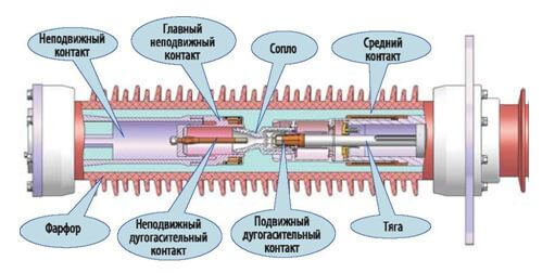
The device and design of the air circuit breaker
Consider how the air circuit breaker is arranged using the example of a VVB power switch, its simplified structural diagram is presented below.
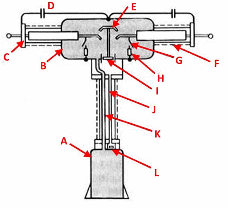
Typical design of VVB series air circuit breakers
Designations:
- A - Receiver, a tank into which air is pumped until a pressure level corresponding to the nominal one is formed.
- B - Metal tank of the arc chute.
- C - End flange.
- D - Voltage divider capacitor (not used in modern switch designs).
- E - Mounting rod of the movable contact group.
- F - Porcelain insulator.
- G - Additional arcing contact for shunting.
- H - Shunt resistor.
- I - Air jet valve.
- J - Impulse duct pipe.
- K - Main supply of air mixture.
- L - Group of valves.
As you can see, in this series, the contact group (E, G), the on / off mechanism and the blower valve (I) are enclosed in a metal container (B). The tank itself is filled with a compressed air mixture. The switch poles are separated by an intermediate insulator. Since high voltage is present on the vessel, the protection of the support column is of particular importance. It is made with the help of insulating porcelain "shirts".


The air mixture is supplied through two air ducts K and J. The first main one is used to pump air into the tank, the second operates in a pulsed mode (supplies the air mixture when the switch contacts are turned off and resets when it is closed).