- CRITERIA AND LIMITS FOR A SAFE STATE
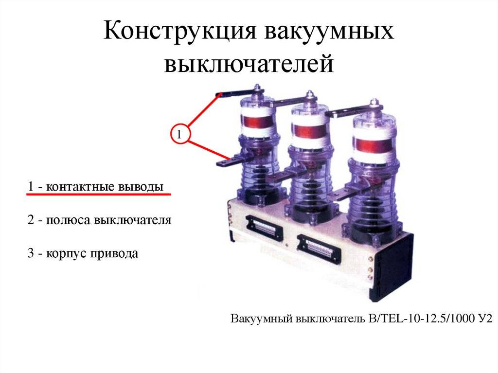
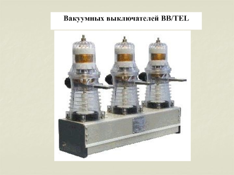
- Vacuum circuit breaker technology.
- History of vacuum circuit breakers
- The most common models
- Turning on the switch
- History of creation
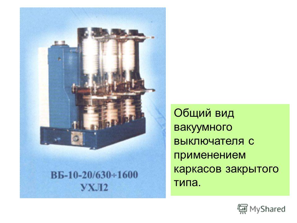
- The device and design of the air circuit breaker
- What is the situation today?
- Thermostatic steam traps (capsular)
- Scope of application
- Principle of operation
- Device Specifications
CRITERIA AND LIMITS FOR A SAFE STATE
Climatic version and placement category U2 according to GOST 1550, operating conditions in this case:
- highest altitude up to 3000 m;
- the upper working value of the ambient air temperature in the switchgear (KSO) is assumed to be plus 55°C, the effective value of the ambient air temperature of the switchgear and KSO is plus 40°C;
- the lower working value of the ambient air temperature is minus 40°С;
- upper value of relative air humidity 100% at plus 25°С;
- the environment is non-explosive, does not contain gases and vapors harmful to insulation, is not saturated with conductive dust in concentrations that reduce the electrical strength parameters of the switch insulation.
Working position in space - any. For versions 59, 60, 70, 71 - base down or up. The switches are designed to work in operations "O" and "B" and in cycles O - 0.3 s - VO - 15 s - VO; O - 0.3 s - VO - 180 s - VO.
The parameters of the circuit breaker auxiliary contacts are given in Table 3.1.
In terms of resistance to external mechanical factors, the circuit breaker corresponds to group M 7 according to GOST 17516.1-90, while the circuit breaker is operational when exposed to sinusoidal vibration in the frequency range (0.5 * 100) Hz with a maximum acceleration amplitude of 10 m / s2 (1 q) and multiple impacts with an acceleration of 30 m/s2 (3 q).
Table 3.1 - Parameters of auxiliary contacts of the circuit breaker
| No. p / p | Parameter | Rated value |
| 1 | 2 | 3 |
| 1 | Maximum operating voltage, V (AC and DC) | 400 |
| 2 | Maximum switching power in DC circuits at t=1 ms, W | 40 |
| 3 | Maximum switching power in AC circuits | 40 |
| 4 | Maximum through current, A | 4 |
| 5 | Test voltage, V (DC) | 1000 |
| 6 | Contact resistance, µOhm, no more | 80 |
| 7 | Switching resource at maximum breaking current, B-O cycles | 106 |
| 8 | Mechanical life, V-O cycles | 106 |
Figure 3.1
The switches meet the requirements of GOST687, IEC-56 and specifications TU U 25123867.002-2000 (as well as ITEA 674152.002 TU; TU U 13795314.001-95).
The dependence of the switching life of the circuit breakers on the magnitude of the current to be switched off is shown in fig. 3.1.


The switches meet the requirements of GOST 687, IEC-56 and specifications TU U 25123867.002-2000 (as well as ITEA 674152.002 TU; TU U 13795314.001-95).
The dependence of the switching life of the circuit breakers on the magnitude of the current to be switched off is shown in fig. 3.1.
Vacuum circuit breaker technology.
The main horizontal coverage line in the "clean room". VIL, Finchley, 1978.
The manufacture of vacuum arc chutes takes place in special installations using modern technologies - "clean room", vacuum furnaces, etc.

Vacuum Circuit Breaker Workshop in South Africa, 1990
The manufacture of a vacuum chamber is a high-tech manufacturing process. After assembly, the circuit breaker chambers are placed in a vacuum oven, where they are hermetically sealed.
Four main points in the production of a vacuum arc chute:
- full vacuum
- detailed calculation of electrical parameters.
- arc control system
- contact group material
Four key points in the production of vacuum circuit breakers:
1. perfect overall build quality of the device.
2. accurate calculation of the electromagnetic parameters of the device. In case of errors in the design of the device, electromagnetic interference between the disconnectors is possible.
3. mechanism. It is necessary to ensure a short stroke of the mechanism and a low level of energy consumption. For example, when switching to 38kV, the required stroke of the mechanism is 1/2″ and, at the same time, the energy consumption does not exceed 150 J.
4. Perfectly sealed welding seams.
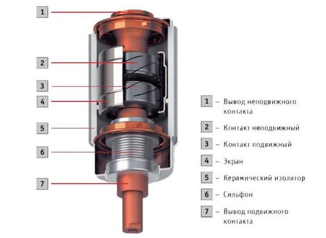
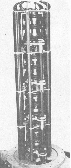
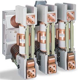
The device of a classical vacuum arc chute.
arc chute V8 15 kV (4 1/2″ dia.). Early 70s.
The photo shows the main components of the design of the vacuum arc chute.
Electric arc control: radial magnetic field.
High-speed shooting frame (5000 frames per second).
breaker pad. diameter 2”.
Radial magnetic field
31.5kArms 12kVrms.
This process occurs due to the self-induction of the radial magnetic field (the field vector is directed along the radial direction), which creates an arc movement over the electrical contact, while reducing the local heating of the contact pad.The material of the contacts must be such that the electric arc moves freely over the surface. All this makes it possible to implement switching currents up to 63 kA.
Arc control: axial magnetic field.
High-speed shooting frame (9000 frames per second).
Image of the axial magnetic field
40kArms 12kVrms
The process using self-induction of the magnetic field along the axis of the electric arc does not allow the arc to shrink and protects the contact pad from overheating, removing excess energy. In this case, the material of the contact area should not contribute to the movement of the arc along the contact surface. There is a possibility in industrial conditions to carry out switching of currents over 100 kA.
An electric arc in a vacuum is the material of contact groups.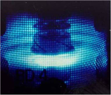
High-speed shooting frame (5000 frames per second).
Image of a pad with a diameter of 35mm.
Radial magnetic field.
20kArms 12kVrms
When the contacts are opened in a vacuum, metal evaporates from the contact surfaces, which forms an electric arc. In this case, the properties of the arc change depending on the material from which the contacts are made.
Recommended parameters of contact plates:
| voltage | product | Requirements |
| 1.2-15 kV | contactor | Minimum trip threshold < 0.5 A |
| 15-40 kV | switch | high dielectric strength – (up to 200 kV at 12 mm) |
| 132 kV and above | switch | very high dielectric strength – (up to 800 kV at 50 mm) |
materials
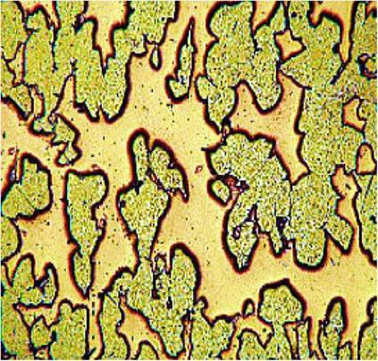
Micrograph.
Initially, an alloy of copper and chromium was used for the manufacture of contact plates. This material was developed and patented by English Electric in the 1960s. Today, it is the most used metal in the production of vacuum arc chutes.


The principle of operation of the mechanism.
The mechanism of vacuum circuit breakers is designed in such a way that the amount of energy spent on switching does not play any role - there is a simple movement of the contacts. A typical automatic reclosure requires 150-200 Joules of energy to control, unlike a gas-insulated backbone switch that needs 18,000-24,000 Joules to make one changeover. This fact allowed the use of permanent magnets in the work.
Magnetic drive.
The principle of operation of the magnetic drive
Resting stage Movement stage is a model of movement.
History of vacuum circuit breakers
50s. History of development: how it all began ...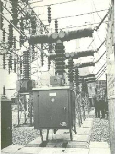
One of the first high-voltage switches of the main electrical network. The photo shows a 132 kV AEI, a vacuum circuit breaker in operation in West Ham, London, since 1967. This, like most similar devices, was in operation until the 1990s.
Development history: 132kV VGL8 vacuum circuit breaker.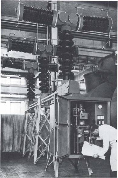
- the result of a joint development of CEGB (Central Power Board - the main supplier of electricity in England) and the General Electric Company.
- the first six devices were put into operation in the period 1967 - 1968.
- the voltage is distributed using parallel-connected capacitors and a complex movable mechanism.
- each group is protected by a porcelain insulator and is pressurized in SF6 gas.
Vacuum circuit breaker configuration "T" with four vacuum arc chutes in each group - respectively, a series of 8 vacuum arc chutes is connected per phase.
Operation history of this machine:
— uninterrupted operation in London for 30 years. In the 1990s, it was withdrawn from service as unnecessary and dismantled.
- vacuum circuit breakers of this type were used until the 1980s at the Tir John power plant (Wales), after which, as a result of network reconstruction, they were dismantled in Devon.
History of development: problems of the 60s.
At the same time, along with the development of high-voltage vacuum circuit breakers, manufacturing companies changed their oil and air circuit breakers to SF6 circuit breakers. SF6 switches were simpler and cheaper to operate for the following reasons:
- the use of 8 vacuum circuit breakers per phase in high-voltage vacuum circuit breakers requires a complex mechanism to ensure simultaneous operation of 24 contacts in a group.
- the use of existing oil circuit breakers was not economically feasible.
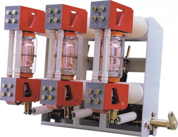
Vacuum switch.
Vacuum circuit breakers first used V3 series vacuum interrupters and later V4 series.
Vacuum arc chutes of the V3 series were originally developed for use in three-phase distribution networks, with a voltage of 12 kV. Nevertheless, they were successfully used in electric traction circuits of electric locomotives and connections in the "right of way" - in single-phase networks, with a voltage of 25 kV.
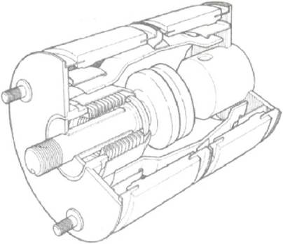
Vacuum circuit breaker device:
The vacuum circuit breaker consists of a 7/8″ (22.2mm) main chamber and an additional 3/8″ (9.5mm) chamber for operating the contact springs.
— the average speed of closing the chamber is 1-2 m/sec.
– average chamber opening speed – 2-3 m/sec.
So what issues were solved by the manufacturers of vacuum high-voltage circuit breakers in the 60s?
Firstly, the switching voltage of the first vacuum circuit breakers is limited to 17.5 or 24 kV.
Secondly, the technology of that time required a large number of vacuum arc chutes in series. This, in turn, entailed the use of complex mechanisms.
Another problem was that the production of vacuum arc extinguishers of that time was designed for large sales volumes. The development of highly specialized devices was not economically feasible.
The most common models
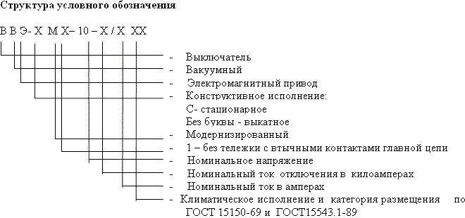
Here are some of the most common models VVE-M-10-20, VVE-M-10-40, VVTE-M-10-20, and the figure shows how to decipher them and legend structure, since models can contain up to 10–12 letters and numbers in their name. Almost all of them are replacements for obsolete oil circuit breakers, and they can work both for switching AC and DC circuits.
Setting up, installing and putting into operation high-voltage vacuum circuit breakers is a laborious process, on which all further operation of the power system, as well as all elements and equipment connected to them, directly depends, so it is better to put all work on the shoulders of qualified electrical engineering personnel.The control of the vacuum circuit breaker must be carried out clearly and according to certain commands, the life and health of people working on powered equipment depends on this.
Turning on the switch
The initial open state of the contacts 1, 3 of the vacuum arc chute of the circuit breaker is ensured by acting on the movable contact 3 of the opening spring 8 through the traction insulator 4. When the “ON” signal is applied, the circuit breaker control unit generates a voltage pulse of positive polarity, which is applied to the coils 9 of the electromagnets. At the same time, an electromagnetic force of attraction appears in the gap of the magnetic system, which, as it increases, overcomes the force of the springs of disconnection 8 and preload 5, as a result of which, under the influence of the difference in these forces, the armature of the electromagnet 7 together with the traction insulators 4 and 2 at time 1 begin to move in the direction fixed contact 1, while compressing the opening spring 8.
After closing the main contacts (time 2 on the oscillograms), the electromagnet armature continues to move upward, additionally compressing the preload spring 5. The movement of the armature continues until the working gap in the electromagnet magnetic system becomes equal to zero (time 2a on the oscillograms). Further, the ring magnet 6 continues to store the magnetic energy necessary to hold the circuit breaker in the closed position, and the coil 9, upon reaching time 3, begins to de-energize, after which the drive is prepared for the opening operation. Thus, the switch becomes on a magnetic latch, i.e. control power to hold contacts 1 and 3 in the closed position is not consumed.
In the process of switching on the switch, the plate 11, which is included in the slot of the shaft 10, rotates this shaft, moving the permanent magnet 12 installed on it and ensuring the operation of the reed switches 13, which commute the external auxiliary circuits.
History of creation
The first development of vacuum circuit breakers was started in the 30s of the XX century, the current models could cut off small currents at voltages up to 40 kV. Sufficiently powerful vacuum circuit breakers were not created in those years due to the imperfection of the technology for manufacturing vacuum equipment and, above all, due to the technical difficulties that arose at that time in maintaining a deep vacuum in a sealed chamber.


An extensive research program had to be carried out in order to create reliable working vacuum arc chutes capable of breaking high currents at high voltage of the electrical network. In the course of these works, approximately by 1957, the main physical processes occurring during arc burning in vacuum were identified and scientifically explained.
The transition from single prototypes of vacuum circuit breakers to their serial industrial production took another two decades, since it required additional intensive research and development aimed, in particular, at finding an effective way to prevent dangerous switching overvoltages that arose due to premature interruption of the current to its natural zero crossing, to solving complex problems related to voltage distribution and contamination of the internal surfaces of insulating parts with metal vapors deposited on them, shielding problems and the creation of new highly reliable bellows, etc.
At present, the industrial production of highly reliable high-speed vacuum circuit breakers capable of breaking high currents in medium (6, 10, 35 kV) and high voltage (up to 220 kV inclusive) electrical networks has been launched in the world.
The device and design of the air circuit breaker
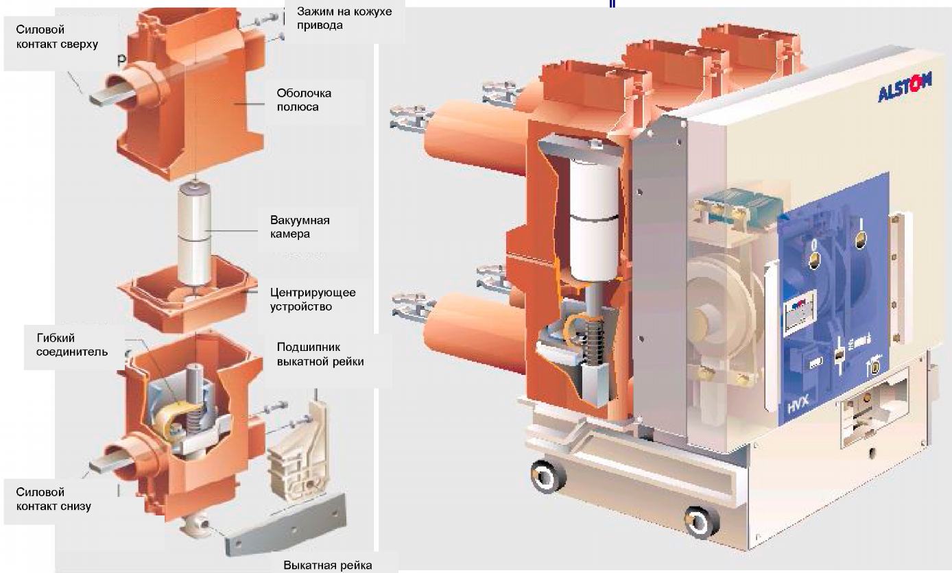
Consider how the air circuit breaker is arranged using the example of a VVB power switch, its simplified structural diagram is presented below.
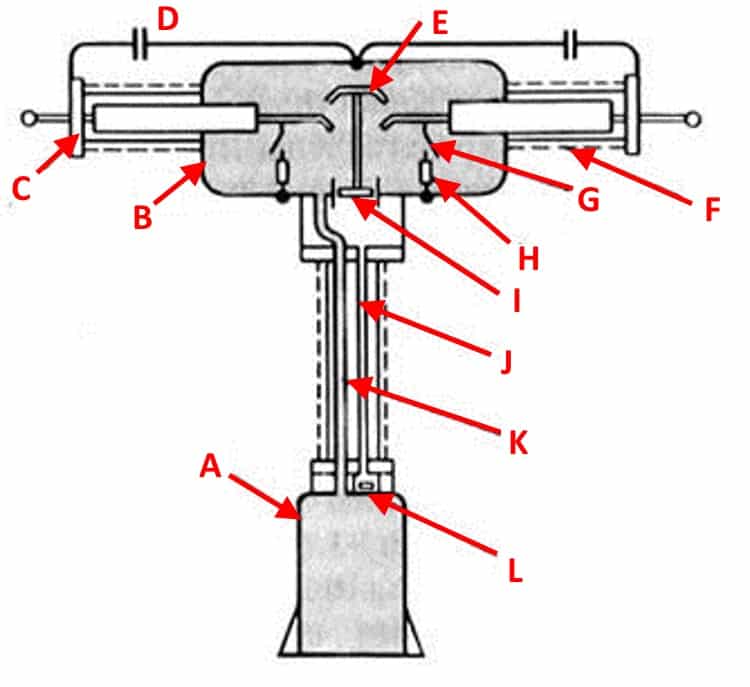
Typical design of VVB series air circuit breakers
Designations:
- A - Receiver, a tank into which air is pumped until a pressure level corresponding to the nominal one is formed.
- B - Metal tank of the arc chute.
- C - End flange.
- D - Voltage divider capacitor (not used in modern switch designs).
- E - Mounting rod of the movable contact group.
- F - Porcelain insulator.
- G - Additional arcing contact for shunting.
- H - Shunt resistor.
- I - Air jet valve.
- J - Impulse duct pipe.
- K - Main supply of air mixture.
- L - Group of valves.
As you can see, in this series, the contact group (E, G), the on / off mechanism and the blower valve (I) are enclosed in a metal container (B). The tank itself is filled with a compressed air mixture. The switch poles are separated by an intermediate insulator. Since high voltage is present on the vessel, the protection of the support column is of particular importance. It is made with the help of insulating porcelain "shirts".
The air mixture is supplied through two air ducts K and J. The first main one is used to pump air into the tank, the second operates in a pulsed mode (supplies the air mixture when the switch contacts and resets when closure).
What is the situation today?
The scientific achievements obtained over the past forty years have made it possible to combine, in the production of a vacuum disconnector, chambers for 38 kV and 72/84 kV into one. The maximum possible voltage on one disconnector today reaches 145 kV - thus, the high level of switching voltage and low power consumption allow the use of reliable and inexpensive devices.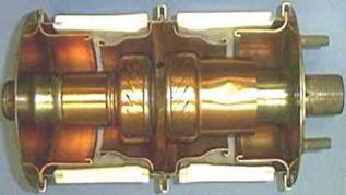
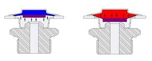
The breaker in the photo on the left is designed to work under voltage of 95 kV, and in the photo on the right it is designed to work under voltage of 250 kV. Both devices are the same length. Such progress has become possible due to the improvement of the materials from which the electrical contact surfaces are made.
Problems that appear when using vacuum circuit breakers on networks with higher voltage:
The operation requires physically large dimensions of the vacuum chamber, which entails a reduction in productivity and a deterioration in the quality of processing of the chambers themselves.
Increasing the physical dimensions of the device increases the requirements for ensuring the sealing of the device itself and for the control of the production process.
A long (longer than 24 mm) gap between the contacts affects the ability to control the arc with a radial and axial magnetic field, and reduces the performance of the device.
The materials used today for the manufacture of contacts are designed for medium voltage values. To work at such large gaps between contacts, it is necessary to develop new materials.
The presence of x-rays must be taken into account.
In connection with the last point, a few more facts should be noted:
When the contactor is switched off, there is no X-ray emission.
At medium voltages (up to 38 kV), X-ray radiation is zero or negligible. As a rule, in voltage switches up to 38 kV, X-ray radiation appears only at test voltages.
As soon as the voltage in the system rises to 145 kV, the power of the X-ray radiation increases and here it is already necessary to solve safety problems.
The question facing designers of vacuum interrupters now is how much exposure will be to the surrounding space, and how this will affect the polymers and electronics that are mounted directly on the switch itself.
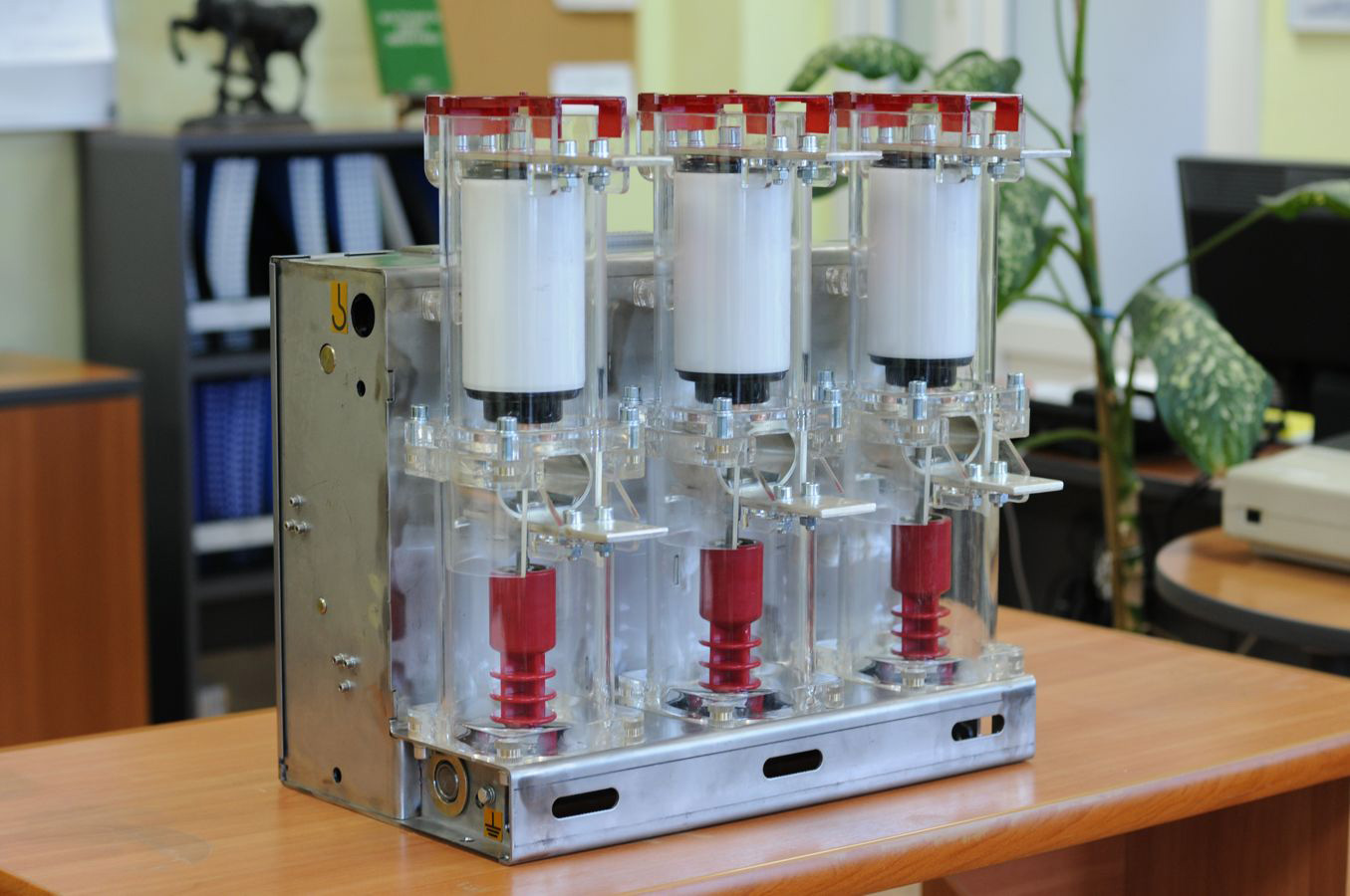
Present day.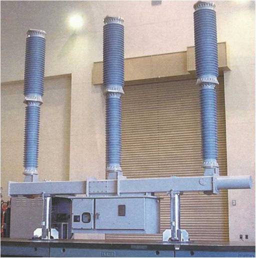
Vacuum high voltage circuit breaker, designed for operation 145 kV.
Modern vacuum arc chute.
The production of a vacuum interrupter designed for operation in 145 kV networks greatly simplifies the production of a 300 kV vacuum circuit breaker. with two discontinuities per phase.However, such high voltage values impose their own requirements on the material of contacts and methods of controlling the electric arc. Conclusions:
Technologically, industrial production and operation of vacuum circuit breakers on networks with voltage up to 145 kV is possible.
Using only technologies known today, it is possible to operate vacuum interrupters on networks up to 300-400 kV.
Today, there are serious technical problems that do not allow the use of vacuum interrupters on networks over 400 kV in the near future. However, work in this direction is underway, the purpose of such work is the production of vacuum arc chutes for operation on networks up to 750 kV.
To date, there are no big problems when using vacuum arc chutes on main lines. Vacuum circuit breakers, for 30 years, have been successfully used in transmission of current on voltage networks up to 132 kV.
Thermostatic steam traps (capsular)
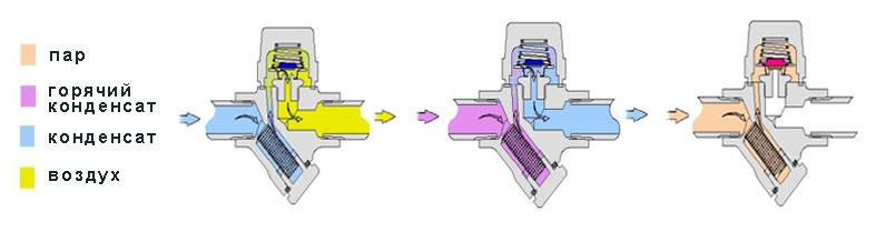
The principle of operation of a thermostatic steam trap is based on the temperature difference between steam and condensate.
The working element of a thermostatic steam trap is a capsule with a seat located in the lower part, which acts as a locking mechanism. The capsule is fixed in the body of the steam trap, with the disk located directly above the seat, at the outlet of the steam trap. When cold, there is a gap between the capsule disc and the seat to allow condensate, air and other non-condensable gases to exit the trap unhindered.
When heated, the special composition in the capsule expands, acting on the disc, which, when expanded, falls on the saddle, preventing steam from escaping. This type of steam trap, in addition to condensate removal, also allows you to remove air and gases from the system, that is, to be used as an air vent for steam systems. There are three modifications of thermostatic capsules that allow you to remove condensate at a temperature of 5°C, 10°C or 30°C below the vaporization temperature.
Main models of thermostatic steam traps: TH13A, TH21, TH32Y, TSS22, TSW22, TH35/2, TH36, TSS6, TSS7.
Scope of application
If the first models, released back in the USSR, provided switching off relatively small loads due to the design imperfection of the vacuum chamber and the technical characteristics of the contacts, then modern models can boast of a much more heat-resistant and durable surface material. This makes it possible to install such switching units in almost all branches of industry and the national economy. Today, vacuum circuit breakers are used in the following areas:


- In electrical distribution installations of both power stations and distribution substations;
- In metallurgy to power furnace transformers supplying steelmaking equipment;
- In the oil and gas and chemical industries at pumping points, switching points and transformer substations;
- For the operation of primary and secondary circuits of traction substations in railway transport, supplies power to auxiliary equipment and non-traction consumers;
- At mining enterprises for powering combines, excavators and other types of heavy equipment from complete transformer substations.
In any of the above sectors of the economy, vacuum circuit breakers are replacing obsolete oil and air models everywhere.
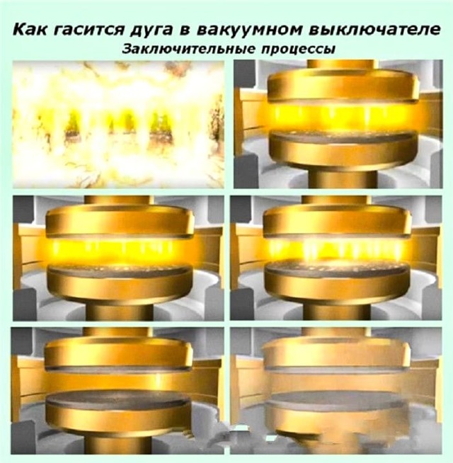
Principle of operation
The vacuum circuit breaker (10 kV, 6 kV, 35 kV - doesn't matter) has a certain operating principle. When the contacts open, in the gap (in vacuum) the switching current creates an electric discharge - an arc. Its existence is supported by the evaporating metal from the surface of the contacts themselves into the gap with vacuum. Plasma formed by vapors of ionized metal is a conducting element. It maintains the conditions for the flow of electric current. At the moment when the alternating current curve passes through zero, the electric arc begins to go out, and the metal vapor virtually instantly (in ten microseconds) restores the electric strength of the vacuum, condensing on the contact surfaces and the insides of the arc chute. At this time, the voltage is restored on the contacts, which by that time had already been divorced. If overheated local areas remain after voltage restoration, they can become sources of emission of charged particles, which will cause a vacuum breakdown and current flow. To do this, arc control is used, the heat flux is evenly distributed on the contacts.
A vacuum circuit breaker, the price of which depends on the manufacturer, due to its performance properties, can save a significant amount of resources. Depending on the voltage, manufacturer, insulation, prices can range from 1500 USD. up to 10000 c.u.
Device Specifications
Devices that switch off the load by opening the electrical circuit have different technical characteristics
All of them are important and become decisive when choosing a unit suitable for purchase and its subsequent installation.
The nominal voltage indicator reflects the operating voltage of the electrical device, for which it was originally designed by the manufacturer.
The maximum operating voltage value indicates the highest possible permissible high voltage at which the circuit breaker is able to operate in normal mode without compromising its performance. Usually this figure exceeds the size of the rated voltage by 5-20%.
The flow of electric current, during the passage of which the level of heating of the insulating coating and parts of the conductor does not interfere with the normal operation of the system and can be sustained by all elements for an unlimited time, is called the rated current. Its value must be taken into account when choosing and buying a load switch.
The value of the through current of the permissible limits shows how much current flowing through the network in the short circuit mode, the load switch installed in the system can withstand.
The electrodynamic resistance current reflects the magnitude of the short-circuit current, which, acting on the device during the first few periods, does not have any negative effect on it and does not mechanically damage it in any way.
The thermal withstand current determines the limiting current level whose heating action for a certain period of time does not disable the switch-disconnector.
Also very important are the technical implementation of the drive and the physical parameters of the devices, which determine the overall size and weight of the device. Focusing on them, you can understand where it will be more convenient to place the devices so that they work correctly and clearly perform their tasks.
Among the unconditional positive qualities of devices responsible for disconnecting the load are the following positions:
- simplicity and availability in manufacturing;
- elementary way of operation;
- very low cost of the finished product compared to other types of switches;
- possibility of comfortable activation/deactivation of rated currents of loads;
- gap between contacts visible to the eye, ensuring complete safety of any work on outgoing lines (installation of an additional disconnector is not required);
- low-cost protection against overcurrent by fuses, usually filled with quartz sand (type PKT, PK, PT).
Of the minuses of switches of all types, the ability to switch only rated powers without operating with emergency currents is most often mentioned.
Despite the low cost and maintenance, autogas modules are considered obsolete and during scheduled maintenance or during the reconstruction of networks and substations they are purposefully replaced with more modern vacuum elements.
Autogas modules are usually reproached for a limited working life due to the gradual burnout of internal parts that generate gas in the arc chute.
However, this moment can be completely solved, and with little money, since the gas generation elements and paired contacts designed for arc absorption are very inexpensive and can be easily replaced, not only by professionals, but also by workers with low qualifications.


