
- Varieties of light bulbs
- Incandescent and halogen lamps
- Low voltage halogen bulbs
- Fluorescent lamps
- LED light bulbs
- When is buying the worst option?
- Dimmer circuits
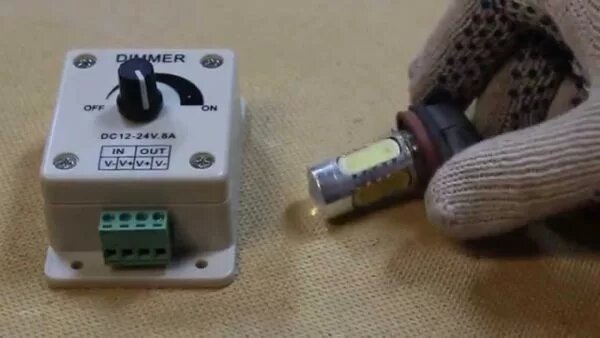
- How to connect LEDs through a dimmer?
- Connecting a dimmer
- Scheme of a dimmer with a switch
- Wiring diagram with two dimmers
- Scheme with two through switches
- Advantages and disadvantages of dimmers
- On the microcontroller
- Dimmers for LED lamps 220 volts. Scheme
- Scheme and principle of its operation
- What you need to know about dimmers?
- Advantages of using the device
- How is regulation carried out?
- Adjustment of lighting in several rooms with a pass-through regulator
- We connect the regulator instead of the switch - procedure
- Using Capacitors
- Principle of operation
Varieties of light bulbs
In dimmers, a variety of types of light sources are used: incandescent lamps, halogen (conventional and low-voltage), fluorescent, LED bulbs. The options for connecting a dimmer with a switch differ depending on the type of lamps used.
Incandescent and halogen lamps
These light sources are rated for 220 volts.To change the intensity of lighting, dimmers of any models are used, since the load is all active due to the lack of capacitance and inductance. The disadvantage of systems of this type is the shift of the color spectrum towards red. This happens when the voltage drops. The power of the dimmers is between 60 and 600 watts.
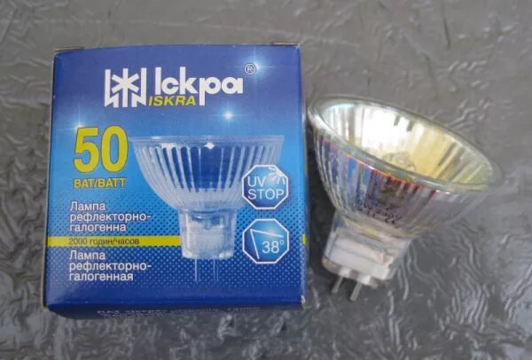
Low voltage halogen bulbs
To work with low voltage lamps, you will need a step-down transformer with a regulator for inductive loads. A distinctive feature of the regulator is the abbreviation RL. It is recommended to purchase the transformer not separately from the dimmer, but as a built-in device. For an electronic transformer, capacitive indicators are set. For halogen light sources, the smoothness of voltage fluctuations plays an important role, otherwise the life of the bulbs will be drastically reduced.
Fluorescent lamps
The standard dimmer will have to be changed to an electronic ballast (electronic ballast) if the start is carried out by a switch, a starting glow charge or an electromagnetic choke. The simplest diagram of a system with fluorescent lamps is shown in the figure below.
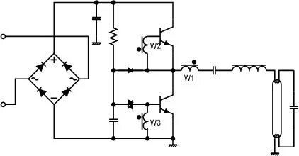
The voltage to the light bulb is sent from a frequency generator of 20–50 kHz. The glow is formed due to the entry into resonance of the circuit created by the inductor and capacitance. To change the current strength (which changes the brightness of the light), you need to change the frequency. The dimming process starts as soon as full power is reached.
Electronic ballasts are made on the basis of the IRS2530D controller, equipped with eight outputs.This device acts as a 600-volt half-bridge driver with triggering, dimming, and fail-safe functionality. The integrated circuit is designed to implement all possible ways control, thanks to the presence of multiple outputs. The figure below shows the control circuit for fluorescent light sources.
LED light bulbs
Although LEDs are economical, it is often necessary to reduce the brightness of their glow.
Features of LED light sources:
- standard plinths E, G, MR;
- possibility of functioning with a network without additional devices (for 12-volt lamps).
LED bulbs are not compatible with standard dimmers. They just fail. Therefore, to work with LEDs, special switches with dimmers for LED lamps are used.
Regulators suitable for LEDs are available in two versions: with voltage control and with control by means of pulse-width modulation. The first type of device is very expensive and bulky (it includes a rheostat or potentiometer). Variable voltage dimmers are not the best choice for low voltage light bulbs and can only operate at 9 and 18 volts.
This type of light source is characterized by a change in the spectrum as a response to voltage regulation. For this reason, the adjustment of light diodes is carried out by controlling the duration of the transmitted pulses. In this way, flickering is avoided, since the pulse repetition rate reaches 300 kHz.
There are such controllers with PWM:
- Modular. Management is carried out by remote controllers, remote controls or using special tires.
- Installed in a mounting box.They are used as switches with rotary or push-button control.
- Remote systems installed in ceiling structures (for LED strips and spotlights).
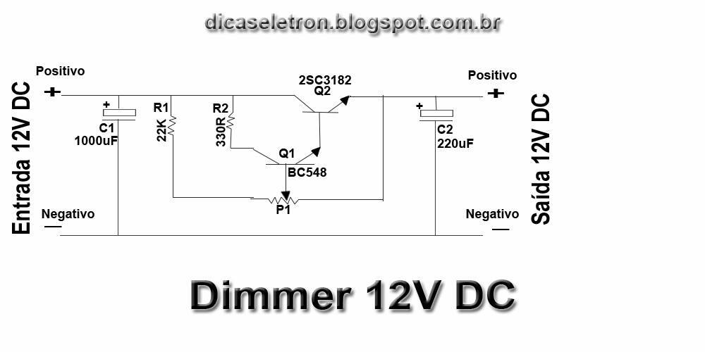
Pulse-width regulation requires expensive microcontrollers. And they are not repairable. It is possible to independently manufacture a device based on a microcircuit. Below is a dimmer circuit for LED bulbs.
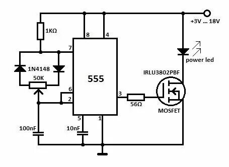
The normal frequency of oscillations is achieved through the use of a generator, which includes a capacitor and a resistor. The intervals for connecting and disconnecting the load at the output of the microcircuit are set by the size of the variable resistor. A field effect transistor serves as a power amplifier. If the current is above 1 ampere, you will need a cooling radiator.
When is buying the worst option?
Factory dimmers are able to provide the expected economic result or increase the comfort of living in all typical situations. In addition, their cost is different, which will allow you to make a purchase "affordable".


But still, in a number of situations, you can not find an option that is suitable in size or power, so a homemade product can be a way out.
In most cases, an interested person will be able to purchase an inexpensive factory dimmer, the performance of which will satisfy him.
There are non-standard situations when industrial products do not satisfy human needs. For example, it happens if a small dimmer is needed, there is a desire to improve the aesthetic properties of its control panel.
Or a person considers it necessary to increase efficiency, make control more convenient, achieve some color effects, improve any other characteristic.
Making a simple dimmer is not a difficult task, all the more you will only need tools available to everyone, the main of which is a soldering iron
And you can also assemble it yourself, when the necessary components are available, which will significantly reduce the cost of the procedure.
Dimmer circuits
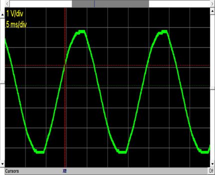
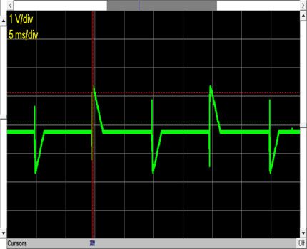
Dimmer for voltage 220V, with a cutoff on the leading edge, works on the principle of phase-pulse voltage control. During operation, the elements of such a dimmer supply voltage to the load at certain moments, cutting off part of the sinusoid. This is shown in more detail and more clearly in the graphs.
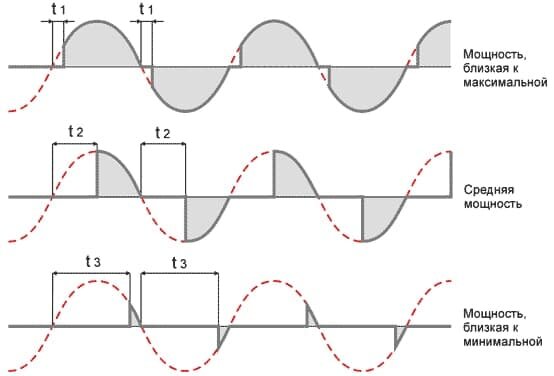
The area of the sinusoid shaded in gray is the area of the voltage or its effective value, which is supplied to the load (lamp or any other device described above).
The red dotted line shows the voltage waveform at the input of the dimmer for led lamps. In this form, it is fed through a conventional switch without adjustments.
How to connect LEDs through a dimmer?
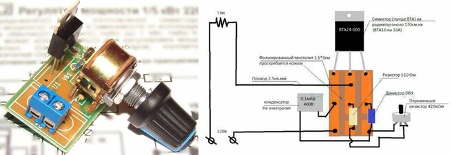
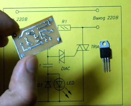
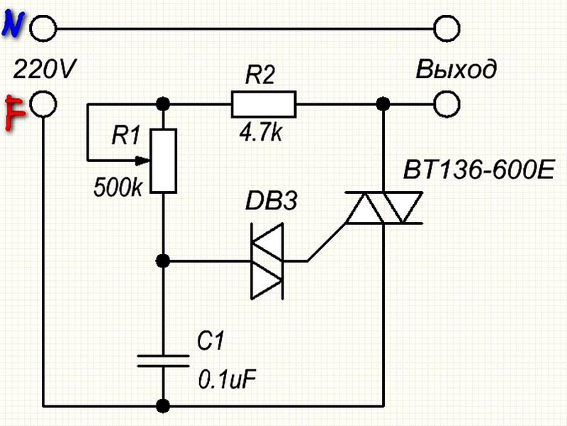
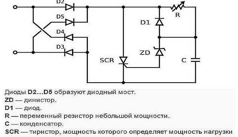
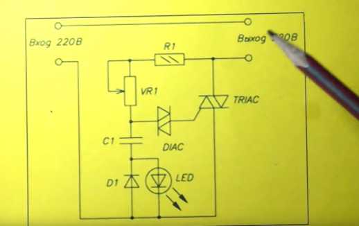
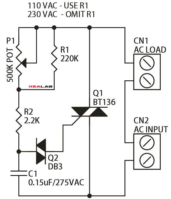
Component ratings and all information are indicated on the dimmer diagram.
The device is installed in the break of the wire going to the light source, engine, heating element or any other device.
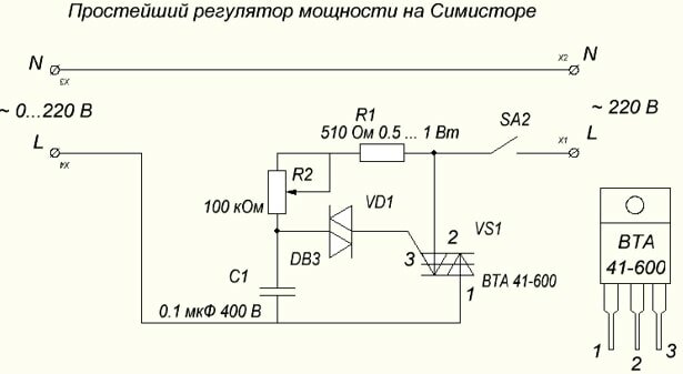
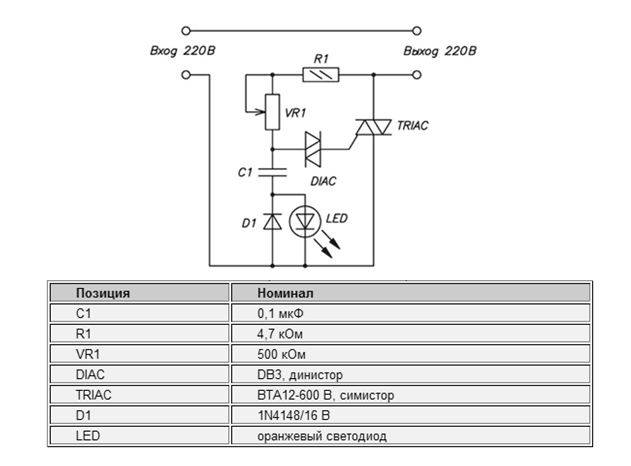
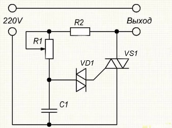
The logic of the circuit is as follows: the capacitor C1 is charged through the circuit R1 and the potentiometer R2. Depending on the position of the potentiometer, the capacitor is charged to the opening voltage of the VD1 dinistor.
The circuit used a DB3 dinistor, which is approximately 30V. Through an open dinistor, a control pulse of the opening of the triac (bidirectional thyristor) is applied to its control electrode.
The greater the resistance set by the potentiometer knob, the longer the capacitor charges, respectively, the later the dinistor-triac circuit will open, and the voltage will be lower, since most of the sinusoid will be cut off. And vice versa - less resistance - more voltage at the output of the regulator.
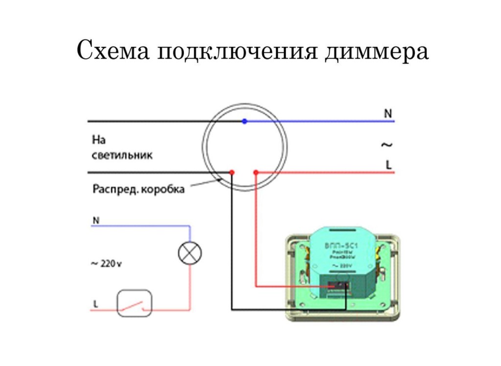
Connecting a dimmer
There are several dimmer connection diagrams.
Scheme of a dimmer with a switch
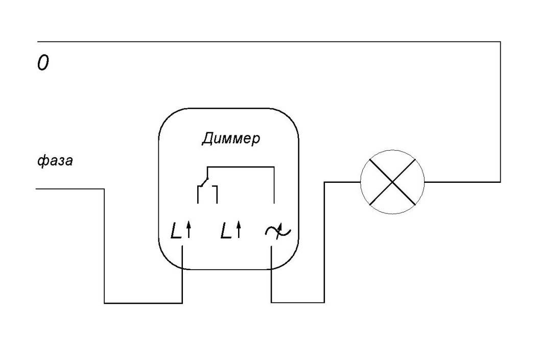
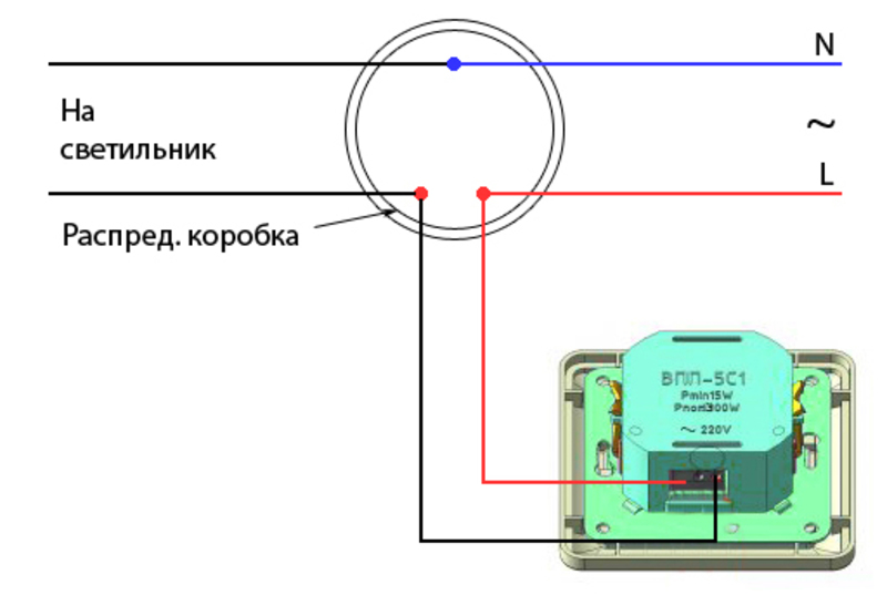
In the described case, the dimmer is installed in front of the dimmer in a phase break. The switch controls the supply of current. The connection diagram is shown in the figure below.
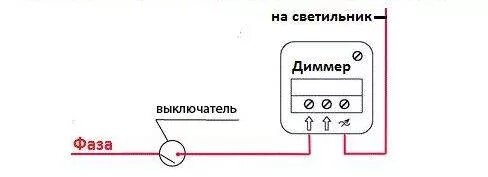
From the switch, the current is directed to the dimmer, and from there to the incandescent bulb. As a result, the regulator determines the desired brightness level, and the switch is responsible for turning the chain on and off.


The scheme is well suited for bedrooms. The switch is placed near the door, and the dimmer is placed near the bed. This makes it possible to control the light directly from the bed. When a person leaves the room, the lighting goes out, and when they return to the room, the light turns on with the characteristics that were set by the dimmer.
Wiring diagram with two dimmers
In this circuit, there are two smooth light switches. They are mounted in two places in one room and, in essence, are walk-through switches that control individual lighting fixtures.
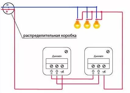
The circuit is associated with the supply of three conductors to the junction box from each point. To connect dimmers, jumpers connect the first and second contacts in the dimmers. Then, a phase is supplied to the third contact of the first dimmer, which goes to the lighting device through the third contact of the second dimmer.
Scheme with two through switches
This scheme is rarely used. It is in demand for organizing control over lighting in walk-through rooms and long corridors. The scheme allows you to turn the light on and off, as well as adjust it from different parts of the room.
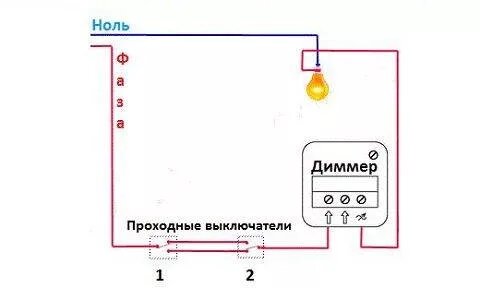
Pass-through switches are placed in a phase break. Contacts are connected by conductors. The dimmer enters the chain in a sequential manner, after one of the switches. A phase approaches the first contact, which then goes to the incandescent lamp.
Brightness is controlled by a dimmer. However, it should be borne in mind that when the regulator is off, the walk-through switches are not able to switch the bulbs.
Advantages and disadvantages of dimmers
Among the advantages of various types of switches with regulators is the smooth start of the lighting system, which can significantly increase the service life of lighting fixtures (the service life of incandescent lamps in this case increases up to 40%).
Dimmers can be used not only to control the light, but also to regulate the voltage of other appliances (kettles, irons, heaters)
In this case, it is important to observe the correspondence between the power of the device and the load exerted on it. Such devices create endless possibilities for interior design.
With their help, it is easy to spotlight the selected area, create interesting light patterns. A valuable quality of dimmers is also the ability to control light sources remotely or with the help of sounds.
Such devices create endless possibilities for interior design. With their help, it is easy to spotlight the selected area, create interesting light patterns.A valuable quality of dimmers is also the ability to control light sources remotely or with the help of sounds.
However, these devices also have their drawbacks. Dimmers can only be used to control light sources whose power corresponds to that of the device. Due to the characteristics of the output voltage, step-down transformers may not work correctly.
The devices may generate electromagnetic interference that will interfere with the operation of radios and other devices. Certain types of lamps (especially those equipped with additional devices - electronic ballast, driver) in principle cannot be combined with dimmers. The efficiency of dimmers when working with incandescent lamps is quite low. Lowering the brightness of the lamps has little effect on the consumption of electricity, which instead of light turns into heat.
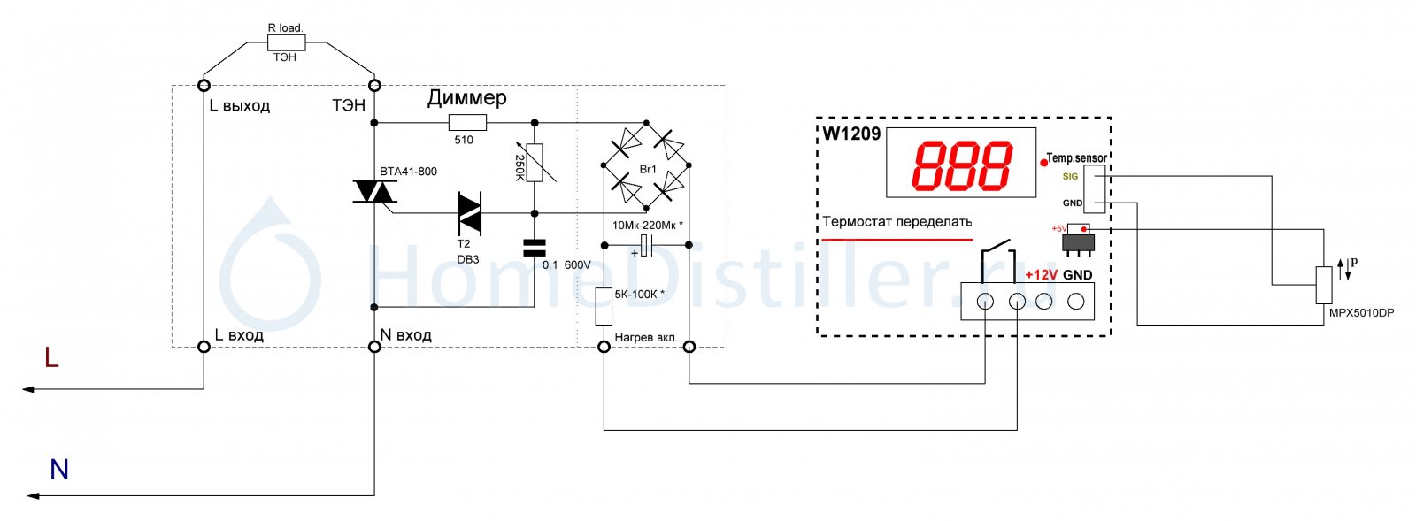
On the microcontroller
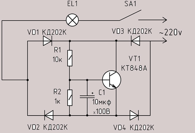
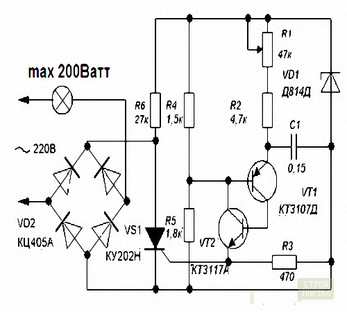
In the event that the performer is completely confident in his abilities, he can take on the manufacture of a heat stabilizer for a soldering iron running on a microcontroller. This version of the power regulator is made in the form of a full-fledged soldering station, which has two working outputs with voltages of 12 and 220 volts.
The first of them has a fixed value and is intended to power miniature low-current soldering irons. This part of the device is assembled according to the usual transformer circuit, which, due to its simplicity, can be ignored.
At the second output of a do-it-yourself regulator for a soldering iron, an alternating voltage operates, the amplitude of which can vary in the range from 0 to 220 volts.
The diagram of this part of the regulator, combined with a PIC16F628A type controller and a digital output voltage indicator, is also shown in the photo.
For the safe operation of equipment with two different output voltages, a home-made regulator must have sockets that are different in design (incompatible with each other).
Such forethought eliminates the possibility of error when connecting soldering irons designed for different voltages.
The power part of such a circuit is made on a triac of the VT 136 600 brand, and the power in the load is adjusted by means of a push-button switch with ten positions.
By switching the push-button regulator, you can change the power level in the load, indicated by numbers from 0 to 9 (these values are displayed on the display of the indicator built into the device).
As an example of such a regulator, assembled according to the scheme with the SMT32 controller, a station designed for connecting soldering irons with T12 tips can be considered.
This industrial design of the device that controls the heating mode of the soldering iron connected to it is able to regulate the temperature of the tip in the range from 9 to 99 degrees.
Dimmers for LED lamps 220 volts. Scheme
In most cases, an interested person will be able to purchase an inexpensive factory dimmer, the performance of which will satisfy him. There are non-standard situations when industrial products do not satisfy human needs. The price of dimmers with a regulator and with buttons differs by an order of magnitude, because a push-button dimmer, for example, a Legrand dimmer, is usually assembled using a microcontroller.


For this, a circuit using a KR EN 12A chip is used, shown in the figure below. Consists of an anode and a cathode.
That is, the power ratio is not 5:1, as in advertising, but 4:1.
The proposed method is suitable for lamps with a capacitor circuit. According to calculations, it should be 10 times more than in the diagram, but then it will not fit into the small lamp body. When connecting a dimmer for an LED lamp in B with remote control, make sure that it is installed directly before the lamp controller. The dimmer in the above configuration is designed to connect an electrical appliance with a power of not more than watts.
And also its functionality allows you to work in conjunction with security systems or simply simulate the presence of people in the room. Read "General Considerations" at the end.
Sting On the sting, too, pay attention when buying. In other words, its resistance becomes very small, and the light bulb burns until the end of the half-wave
When the voltage on the capacitor reaches a value sufficient to open the triac and dinistor, the triac opens.
Scheme and principle of its operation
Its most important advantage is the ability to work in a wide range of supply voltage. In addition, a multi-layer conductor design is provided, which allows you to perform tasks as accurately as possible.
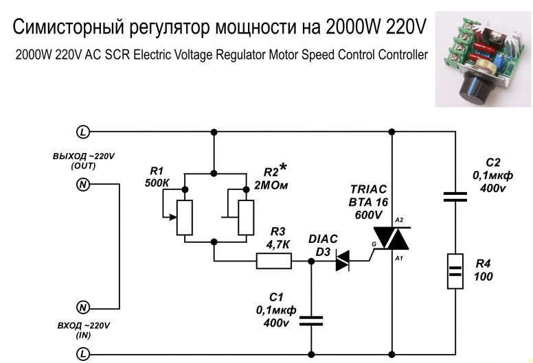
Stupid question. In another way, it is called an AC power regulator. We test the circuit on lamps.
Power regulator for devices powered by AC 220V. Dimmer on VTA41-600
What you need to know about dimmers?
The verb "to dim" in English means "to become dim", "to darken". This phenomenon is the essence of dimmers. In addition, a person additionally receives a number of advantages.
Advantages of using the device
Among the advantages, the following additional features should be highlighted:
- reduce electricity consumption - this leads to greater efficiency;
- replace several types of lighting fixtures - for example, one lamp can serve as a night lamp, main lighting, etc.
In addition, the user can get various lighting effects, for example, use conventional lighting controlled by a dimmer as light music.
And also its functionality allows you to work in conjunction with security systems or simply simulate the presence of people in the room. That will help the owners of any premises protect their property from intruders or even prevent their unauthorized entry into an apartment or office.
The basis of the design of the dimmer is a triac
It is important to remember that its power should be 20-50% higher than the same load indicator. In addition, it must withstand a voltage of 400 V
This will ensure the durability of the product.
Additionally, the brightness control is able to make the control of lighting sources, other electrical appliances more convenient and efficient. For example, you can use radio or infrared signals, which will allow you to perform the necessary manipulations remotely.
Or it is possible to use several light control points instead of one. For example, if the user wants to modernize the lighting in the bedroom, then the regulators can be installed at the entrance there, as well as near the bed.
Such a decision will make the life of the owners somewhat more comfortable. You can do the same in any other room.
How is regulation carried out?
If an interested person decides to assemble a dimmer on his own, then the procedure should be started not with thoughts about how to do it, but with determining the goals and objectives that will be solved.
This is what an ordinary current sine wave looks like, and the essence of dimming is to “cut off” it. This will reduce the duration of the pulse and allow the appliance to operate at less than full power.
So before proceeding with the assembly, it is necessary to decide what type of lamps will be used. This procedure is mandatory, because there are different principles for controlling the brightness of the glow.


These include:
- voltage change - this method will be relevant when using outdated incandescent lamps;
- pulse-width modulation - this option should be used to control the brightness of modern energy-saving lighting devices.
Changing the voltage of LED lamps is ineffective due to the fact that they operate in a narrow range and, with a slight deviation from the norm, they simply go out or do not turn on. That will not allow you to fully unlock the potential of conventional devices, because specialized dimmers for LED devices are produced for them.
In addition, the use of simple but outdated rheostats does not make it possible to save on electricity. After all, excess electricity in the form of heat is simply dissipated in the air.
A properly made dimmer should provide just such a sinusoid, in which short pulses alternate with long pauses. Moreover, the longer it is, and the signal strength is less, the dimmer the lamp will glow.
With the help of pulse-width modulation, it will be possible to assemble a dimmer that provides the lamps with the ability to operate at 10-100% of their power. In this case, the user will receive a pleasant bonus in the form of saved electricity.
And you can also fully use all the other advantages of dimmers, including durability.
Adjustment of lighting in several rooms with a pass-through regulator
Pass-through dimmers are usually used in private households or multi-room apartments. Pass-through switches can be used to solve this problem in order to provide light control.
To be able to adjust the brightness from different places, the pass-through device must be installed at one point, and a rotary dimmer is mounted at another. Such a scheme is one of the simplest in terms of implementation.
At one point in the room, the light will be turned on or off, and at the other, the intensity parameter will be adjusted.
But on sale you can find modern models of devices with the help of pass-through dimming of lighting. These are touch controls. Such devices have electronic filling, which allows you to synchronize the work of several devices at the same time. To control the adjustment procedure by means of dimmers, the devices must first be connected to the so-called satellites. Depending on the type of device, their number can be from 5 to 10 pieces.
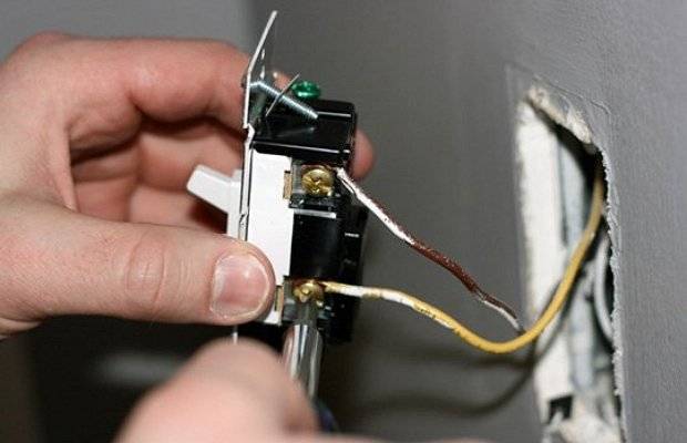
We connect the regulator instead of the switch - procedure
The presence of a home master with minimal knowledge in the electrical field will allow him to correctly connect a monoblock dimmer in his home. There are no particular difficulties here.The main thing to remember is that the regulator is mounted exclusively in the break of the phase cable. Under no circumstances should the device be connected to a neutral break. If you make this mistake, you can immediately go buy a new dimmer. His electronic circuit will simply burn out.
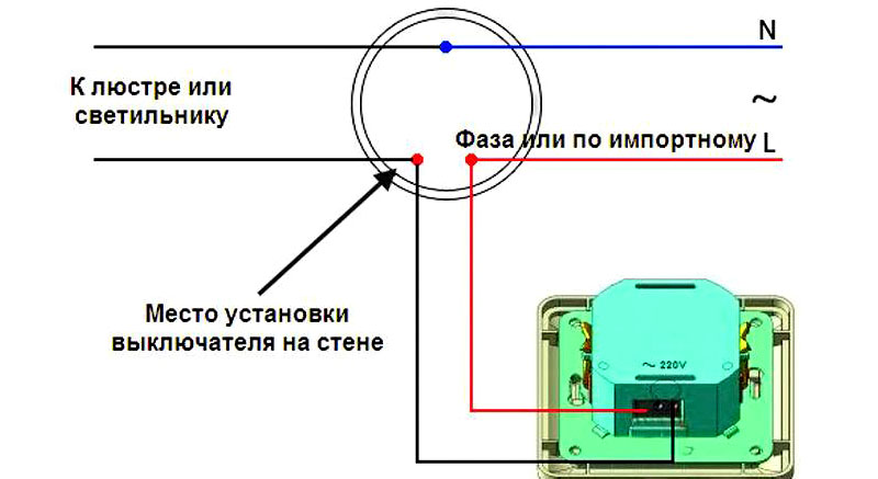
Instead of a switch, the dimmer is installed according to the following scheme:
- Turn off the electricity supply to the apartment in the power panel.
- Disconnect the wires from the terminals of the installed switch and remove it.
- Apply power to the shield, use a screwdriver with an LED, a multimeter or an electrical tester to determine the phase wire. Mark it in a way convenient for you (stick a piece of adhesive tape or electrical tape, put a mark with a pencil).
- Now you can turn off the shield and proceed directly to the installation of the dimmer. It's easy to do. You need to apply the phase wire that you noted to the input of the regulator. From the output, it will go to the junction box (that is, to the load), and then to the lighting fixture itself.
Installing a dimmer
There are dimmers with signed output and input contacts. In them, it is imperative to supply a phase wire to the appropriate connector. If the contacts on the dimmer are not marked in a special way, the phase is fed to any of the available inputs.
After connecting the dimmer, you need to install it back into the socket, put a decorative trim and a potentiometer wheel on the dimmer (if you are mounting a turn-and-push or turn mechanism). All! You were able to properly connect the dimmer to the switch. Use the installed device to your pleasure!
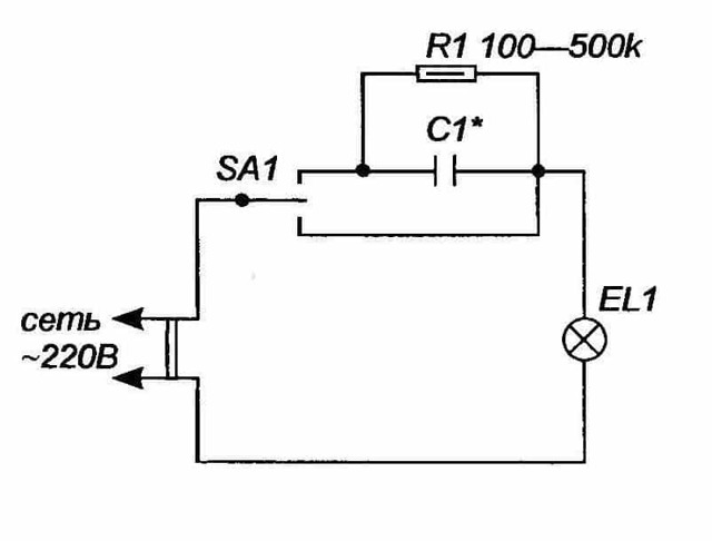
Using Capacitors
Such a dimmer works only as a switch, which changes the path of the current flow that feeds the load. But the button dimmer circuit is quite simple and does not require any specific elements.
Capacitor dimmer circuit
The principle of its operation is to switch the SA1 switch to one of three possible positions:
- off - the circuit is completely broken, the lamp is off or the pass switch outputs a logical zero in the circuit;
- shorted to the lamp - there are no elements in the dimmer connection circuit except for an electric lamp (the lighting device burns at full power);
- connected via R - C circuit - gives out only a certain percentage of lighting brightness.
Depending on the parameters of the resistor and the capacitive element, the voltage and brightness of the glow will depend. This dimmer is used to dim the lighting by dissipating some of the power in the R-C circuit, so you don't get any savings from the dimming.


Principle of operation
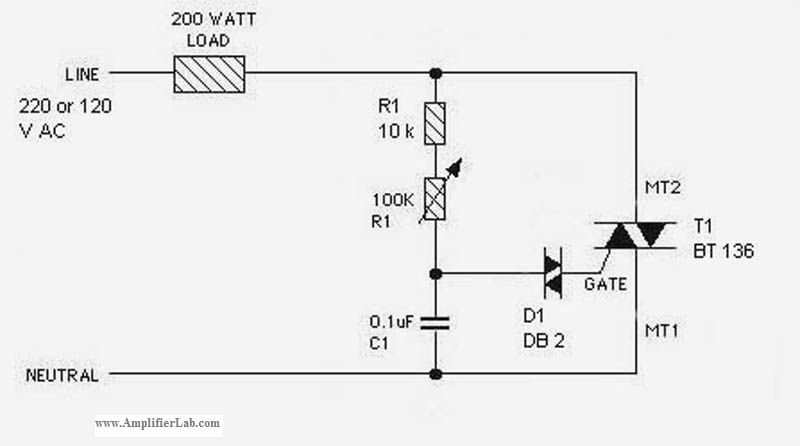
The main element that is present in modern dimmers is a triac. In the English version, it is called a triac. A triac is a semiconductor device that is a type of thyristor. Its main purpose is further switching of AC circuits. On these devices, you can create a dimmer to adjust the voltage in the lighting circuit. For conventional lamps, this is 220 volts and 12 volts for low-voltage halogen lamps. In principle, you can create regulators for almost any voltage.
The triac is connected in series in one circuit with an adjustable load. If there is no control signal on the triac, it is locked and the load is turned off.After a signal is received, the device opens and the load is switched on. A characteristic feature of the triac is that in the open state it will pass current in both directions.
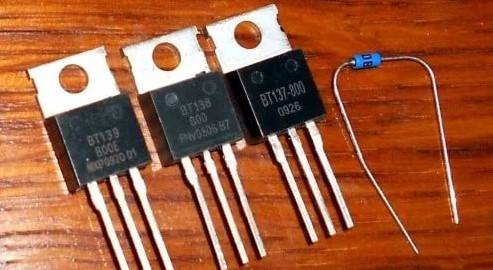
Triac for dimmer
In addition to triacs, the dimmer circuit can also include dinistors, which are a certain type of semiconductor diodes. They serve as controls. Thanks to all the features of the triac and dinistor that we indicated above, the electrical circuits of homemade dimmers are quite simple and contain only a few components.


