- Typical errors when connecting differential automata
- Protection options for a single-phase network
- Option #1 - common RCD for 1-phase network.
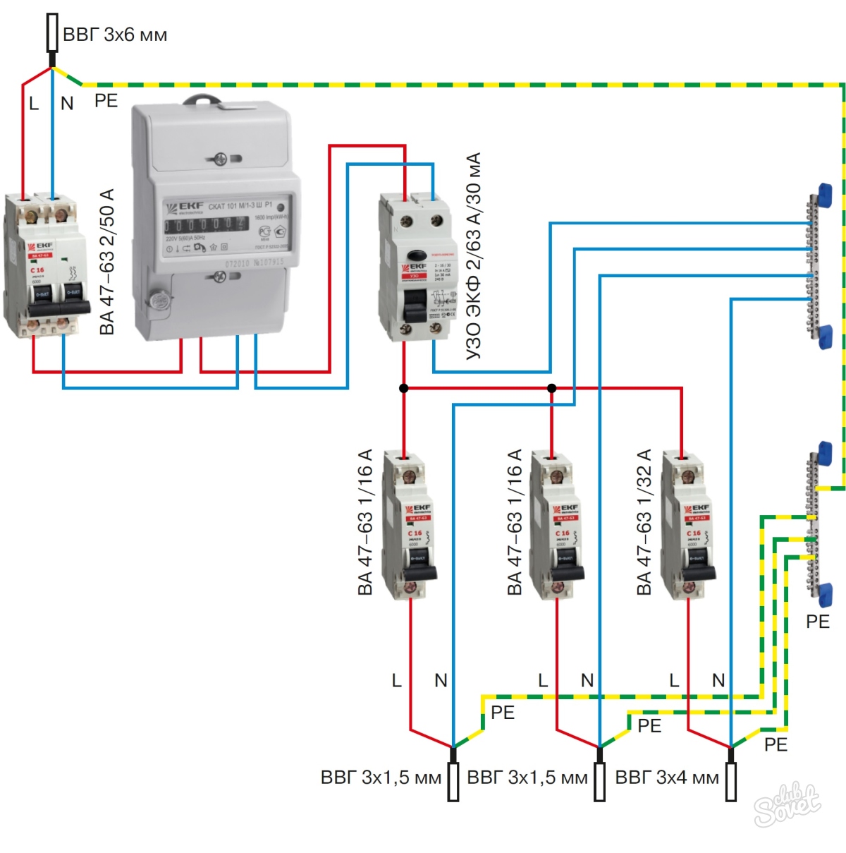
- Option #2 - common RCD for 1-phase network + meter.
- Option #3 - common RCD for 1-phase network + group RCD.
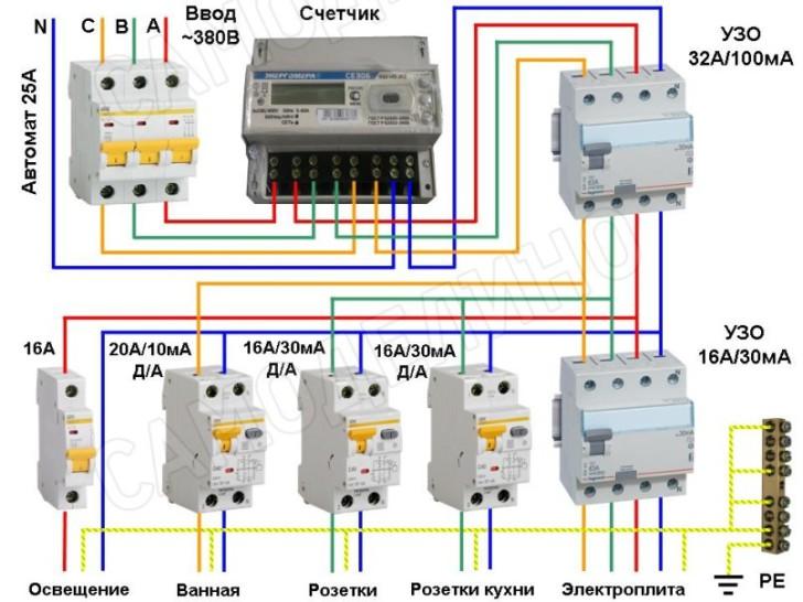
- Option #4 - 1-phase network + group RCDs.
- Device and principle of operation
- Installing a differential switch
- Installation of circuit breakers
- The concept of a differential automaton
- The purpose of the differential machine
- The device of the differential machine
- Manufacturers of differential machines
- Wiring diagrams
- Introductory machine
- Separate machine
- Where to install?
- The process of installing automation in an electrical panel: step by step instructions
- Safety rules in the process of work
Typical errors when connecting differential automata
It makes sense to draw the attention of readers to those errors when installing difavtomatov, which are made quite often and lead either to the inoperability of the circuit, or even to the failure of the protection device.
Error Description
Illustration
Characteristic symptoms
When connecting a difavtomat, the specified location of the input and output wires to the load is violated (if the model is not universal in this matter)
The estimation of the differential current is carried out incorrectly.Unsystematic operation, incorrect operation, refusal to turn on.
The direction of connecting the wires is reversed - phase in one direction, zero in the other.
Instead of mutual compensation, the magnetic fluxes on the core of the differential transformer are superimposed and the control winding detects the differential current even when there is none.
The "test" button may work normally, but when the load is turned on, the RCBO switches off instantly.
On some section of the circuit (it doesn’t matter which one) it is allowed to combine the working zero with the ground loop
Current leakage is set by default. ADVT cannot be turned on at all - the protection immediately works.
Zero on the load was started not from the RCBO, but from a common bus, located according to the scheme above the difavtomat
Estimated differential current incorrect
ADVT turns on, the test passes normally, but when the load is turned on, the protection is triggered instantly.
After difavtomat zero the wire does not go directly to load, and returns to the common zero bus. And only then goes to the load line
The estimate of the differential current is incorrect - practically no current passes through the neutral conductor of the RCBO. The device turns on, but the test does not work, and when you try to turn on the load, protection is instantly triggered
When using two differential automata, a mistake was made - the neutral wires of different lines were mixed up
The estimation of the differential current on both lines becomes incorrect. Difamats turn on, they react normally to passing the test. But any connection of the load at least on one line leads to the operation of the protection on both RCBOs.
Again, when using two (or more) differential automata - below, according to the scheme, it is allowed, erroneously or intentionally, to combine the zeros of individual lines
The estimation of the differential current in both lines is performed incorrectly. RCBOs turn on, but when you press the “test” button on any of them, both turn off at once. And when the load is connected to any line, the differential protection immediately trips on both devices.
* * * * * * *
So, the device and classification of differential current circuit breakers, the main schemes for their inclusion in a home or apartment electrical network, and often made mistakes during their switching were considered.
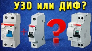
Finally, we can add that difautomats still do not enjoy the special love of electricians. Many masters prefer to get by with the installation of protection assembled from RCDs and circuit breakers. The scheme turns out to be more flexible and maintainable, and given the high cost of RCBOs, it is also more cost-effective.
You can read more about this in a special article on our portal, which is called “What is better, RCD or difavtomat?»
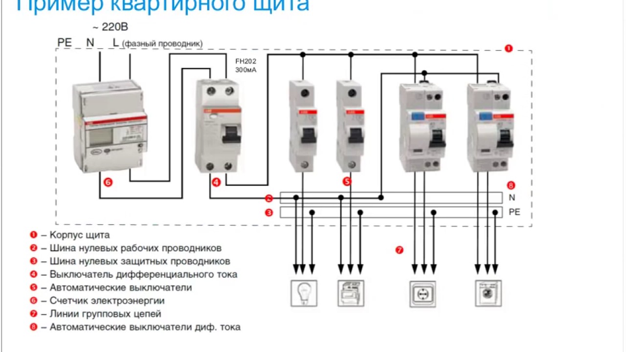
Protection options for a single-phase network
Manufacturers of powerful household appliances mention the need to install a set of protective devices. Often, the accompanying documentation for a washing machine, electric stove, dishwasher or boiler indicates which devices need to be additionally installed in the network.
However, more and more often several devices are used - for separate circuits or groups. In this case, the device in conjunction with the machine (s) is mounted in a panel and connected to a certain line
Considering the number of different circuits serving sockets, switches, equipment that loads the network to the maximum, we can say that there are an infinite number of RCD connection schemes. In domestic conditions, you can even install a socket with built-in RCD.
Next, consider the popular connection options, which are the main ones.
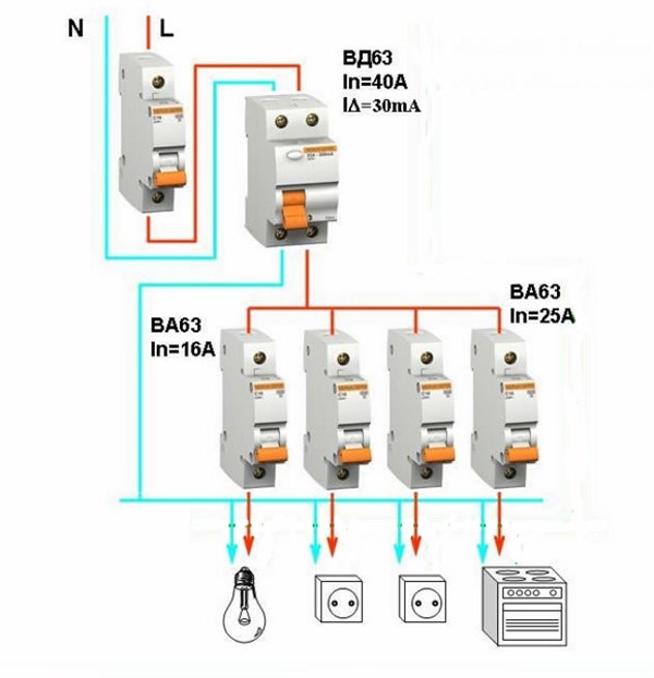
Option #1 - common RCD for 1-phase network.
The place of the RCD is at the entrance of the power line to the apartment (house). It is installed between a common 2-pole machine and a set of machines for servicing various power lines - lighting and socket circuits, separate branches for household appliances, etc.
If a leakage current occurs on any of the outgoing electrical circuits, the protective device will immediately turn off all lines. This, of course, is its minus, since it will not be possible to determine exactly where the malfunction is.
Let's assume it happened current leakage due to contact of the phase wire with a metal device connected to the network. The RCD trips, the voltage in the system disappears, and it will be quite difficult to find the cause of the shutdown.
The positive side concerns savings: one device costs less, and it takes up less space in the electrical panel.
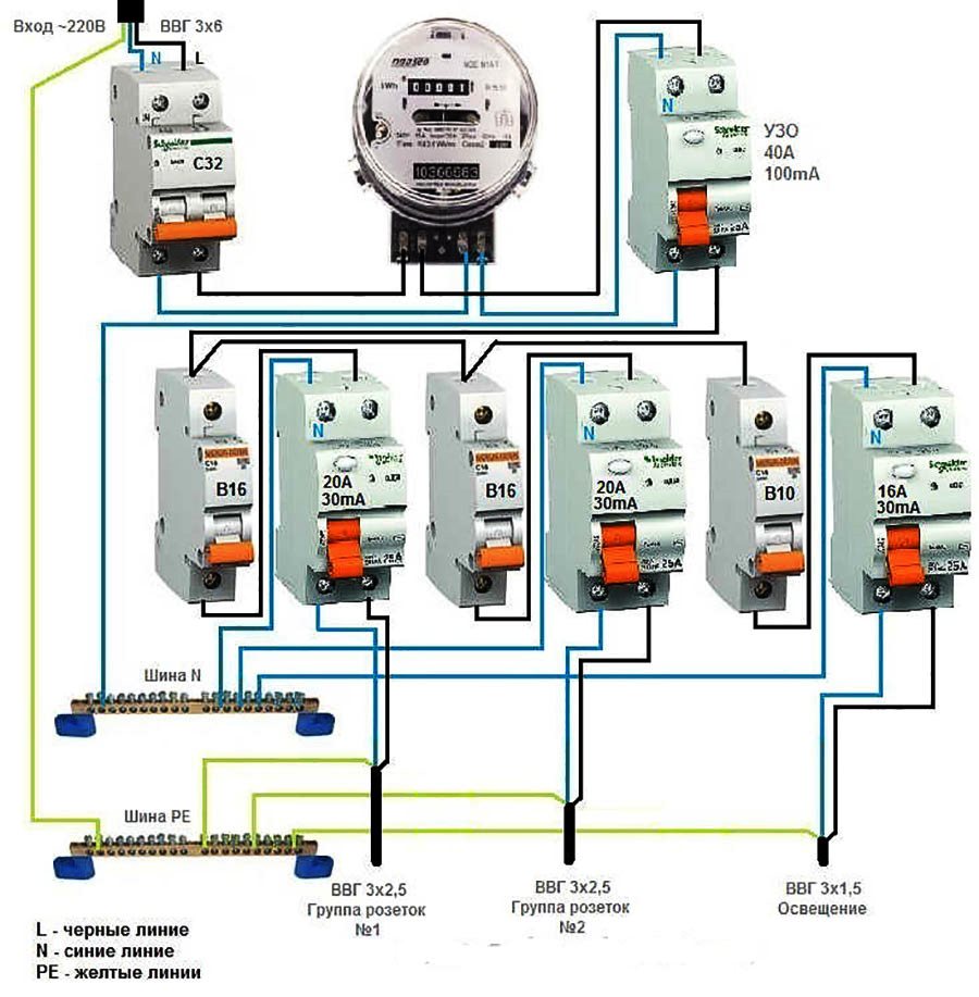
Option #2 - common RCD for 1-phase network + meter.
A distinctive feature of the scheme is the presence of an electricity meter, the installation of which is mandatory.
Current leakage protection is also connected to the machines, but a meter is connected to it on the incoming line.
If it is necessary to cut off the power supply to an apartment or house, they turn off the general machine, and not the RCD, although they are installed side by side and serve the same network
The advantages of this arrangement are the same as those of the previous solution - saving space on the electrical panel and money. The disadvantage is the difficulty of detecting the place of current leakage.


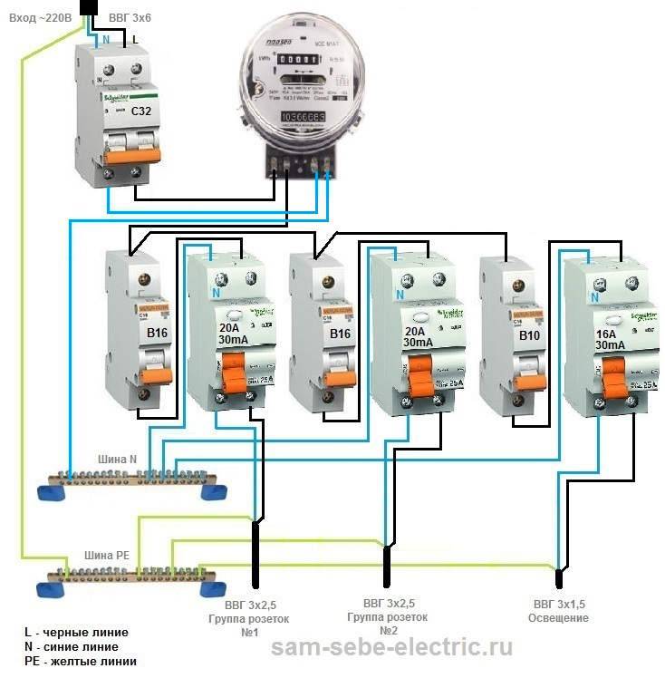
Option #3 - common RCD for 1-phase network + group RCD.
The scheme is one of the more complicated varieties of the previous version.
Thanks to the installation of additional devices for each working circuit, protection against leakage currents becomes double. From a security point of view, this is a great option.
Suppose an emergency current leakage occurred, and the connected RCD of the lighting circuit for some reason did not work. Then the common device reacts and disconnects all lines
So that both devices (private and common) do not immediately work, it is necessary to observe selectivity, that is, when installing, take into account both the response time and the current characteristics of the devices.
The positive side of the scheme is that in an emergency one circuit will turn off. It is extremely rare that the entire network goes down.
This can happen if the RCD installed on a particular line:
- defective;
- out of order;
- does not match the load.
To avoid such situations, we recommend that you familiarize yourself with the verification methods RCD for performance.
Cons - the workload of the electrical panel with a lot of the same type of devices and additional expenses.
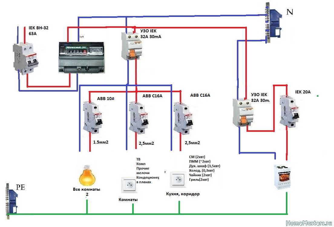
Option #4 - 1-phase network + group RCDs.
Practice has shown that the circuit without installing a common RCD also functions well.
Of course, there is no insurance against the failure of one protection, but this can be easily fixed by purchasing a more expensive device from a manufacturer you can trust.
The scheme resembles a variant with general protection, but without installing an RCD for each individual group. It has an important positive point - it is easier to determine the source of the leak here
From the point of view of economy, the wiring of several devices loses - one common one would cost much less.
If the electrical network in your apartment is not grounded, we recommend that you familiarize yourself with the connection diagrams RCD without grounding.
Device and principle of operation
Difavtomat refers to complex electrical equipment. In fact, it consists of several autonomous structural components. Among them:
- Automatic shutdown system. Controls the load current. When the maximum values are reached, for example, in the event of a short circuit or excessive power of electricity consumers, it works in 0.06 seconds. In case of current leakage as a result of wiring exposure (insulation breakdown) or other problems in cables and wires, the network breaks with a delay of up to 1 hour. Switching off is carried out by magnetic and thermal releases. The speed of the process depends on the magnitude of the current deviation from the standard value. The machine is activated when the difference between the current and rated currents is above 25%.
- differentiated transformer. Designed to protect people and animals from electric shock. The work is based on the use of an electromagnetic coil. When the difference between the incoming and outgoing currents of critical values \u200b\u200bis reached, the coil instantly breaks the circuit.
- Rail for manual switching of the device. It has two positions - on and off. It is used for repair and maintenance work, as well as for connecting power consumers.
Installing a differential switch
 The installation of the difavtomat is carried out in strict accordance with the requirements of the PUE (Electrical Installation Rules). The device is placed in the switchboard on Din - rails, to which it is attached using special clips - latches. The compact housing is made of dielectric material. Polymer composites are often used, which have the properties necessary for electrical devices: strength, thermal and corrosion resistance, and increased fire resistance.
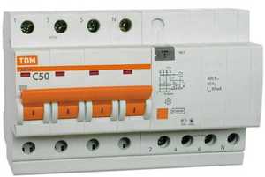 The switch is attached to the shield in such a way that the input wires are on top. The correct mounting direction is shown on the box body. Connected wires at the ends are exposed and stripped with a special tool stripping. High-tech devices are sensitive. Even minor damage to the core of the wire will lead to incorrect operation of the protection system. At a minimum, the number of false trips of the switch will increase.
Phase and neutral wires must be connected to the device through special cells. There are cases when the cores are connected to the product, bypassing the machine. Such a connection scheme is fraught with dangerous consequences.
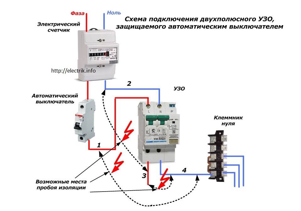
 A gross mistake is to connect the neutral wire at the output of the device with other zeros on the electrical panel. Passing currents will exceed the rating for the device, causing unreasonable tripping. The same effect occurs when zero is connected to ground. This scheme is outdated. It is suitable for two-wire networks with a rough protection system.
With two or three elements in the mains, it is necessary to ensure that the phases and earth are connected correctly.Often, a phase wire is connected to an energy consumer from one device, and zero from another, which eliminates the possibility of protecting the network.


Installation of circuit breakers
The connection of circuit breakers in the switch cabinet is carried out in a certain sequence. From above, a cable is connected to an external current source, and through the output holes located below, the wiring is routed to its objects, in accordance with the electrical circuit.
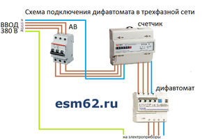
At the beginning of the installation, an introductory machine is connected. If there are several lines isolated from each other, they are separated from the introductory circuit breaker. Its power must not be less than the total power of the machines connected to separate lines. For this purpose, two- or four-pole devices of group D are selected that are resistant to the inclusion of power tools and other powerful equipment.
The most widespread suitable for any power supply schemes for apartments and private houses. Modular circuit breakers are mounted on a DIN rail and connected by conductors with a current carrying capacity exceeding the operating current of the circuit breaker. A more convenient connection of several machines in one row can be performed using a special connecting bus. A piece of the required length is cut off from it and fixed in the terminals. Such a connection is possible due to the distance between the bus contacts, corresponding to the standard width of the modular machines. The switch is installed on the phase, and the neutral conductor is supplied from the input device directly to the devices.
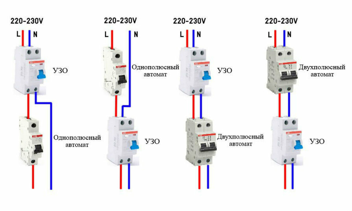
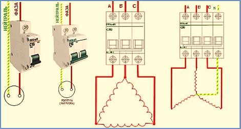
- single pole
the switch is used in the installation of sockets and lighting systems. - Bipolar
the machine is suitable for high power appliances, such as an electric stove or a boiler. In case of overloads, it is guaranteed to break the circuit. The connection diagram of such switches is practically no different from single-pole models. For more efficient use, it is recommended to connect them to a separate line. - Three-pole
the circuit breaker should be installed only in cases where it is planned to use electrical appliances operating at a voltage of 380 V. In order to exclude, the load is connected according to the "triangle" scheme. This connection does not require a neutral conductor, and the consumer is connected to his own switch. - four-pole
the circuit breaker is most often used as an input. The main condition for connection is the uniform distribution of the load on all phases. When connecting equipment according to the “star” scheme or three separate single-phase wires, excess current will flow through the neutral conductor.
With a uniform distribution of all loads, the neutral wire begins to perform a protective function in case of unforeseen power imbalances. To ensure a normal connection, only high-quality materials should be used. All connections must be securely fastened to the terminals. If several cables are connected at once, their contacts must be carefully cleaned and tinned.
The order of actions during the connection can be seen on the example bipolar circuit breakerinstalled in the shield. First of all, the electricity is turned off in order to completely de-energize the network. The absence of electricity is checked with an indicator screwdriver or a multimeter.Then the machine must be installed on a DIN rail and snapped into place. The absence of a mounting rail can create certain inconveniences. After that, the cores of the incoming and outgoing wires are cleaned to a distance of 8-10 mm.
Introductory wires are connected to two clamps located on top -. In the lower clamps, similar outgoing conductors are fixed, distributed to sockets, switches and electrical appliances. All wires are qualitatively clamped in the terminals with screws. The connections must be checked manually. To do this, the conductors must be gently moved from side to side. In the event of a poor-quality connection, the core will stagger in the terminal and may even jump out of it. In this case, the terminal screw must be tightened.
Upon completion of installation, voltage is applied to the network and the operability of the circuit breaker is checked.
The concept of a differential automaton
A differential machine is a combined electrical device designed to operate in low voltage networks and combines the functions of a residual current device (RCD) and a circuit breaker.
The purpose of the differential machine
A difavtomat, also called an automatic differential current switch (RCB), serves to protect the section of the electrical circuit connected by means of this automatic machine to the supply network from failure in the event of increased currents arising in this network. for overloads and short circuits. This function is identical to the purpose of the circuit breaker.
In addition, the differential circuit breaker can prevent fires and injury to people and animals (possibly fatal), arising due to leakage of electric current through damage in the insulating layer of the conductor or a faulty power receiving device, which coincides with the functionality of the RCD.
Important! The main advantage of a differential automaton over these two devices in the aggregate is its compactness. This is especially true if it is necessary to install a number of circuit breakers in the switchboard.
Differential machine
Differential circuit breakers are widely used to protect electrical systems both in everyday life and in office and industrial premises. They are in no way inferior in their characteristics to similar RCDs and circuit breakers, therefore, they do not have any special restrictions in terms of scope. It is possible to install difautomats both at the entrance to the building and on branch cable routes for fire safetyand the safety of people and other living organisms.
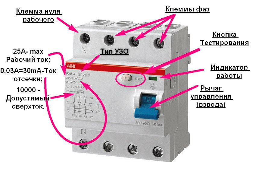
The device of the differential machine
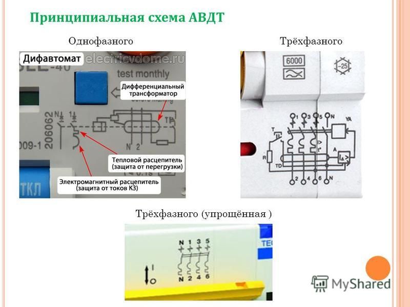
The main working elements of the difavtomat design are:
- differential transformer;
- electromagnetic release;
- thermal release.
Transformer included differential circuit breaker, has several windings, the number of which directly depends on the number of poles of the device. It is designed to compare the load currents of conductors.


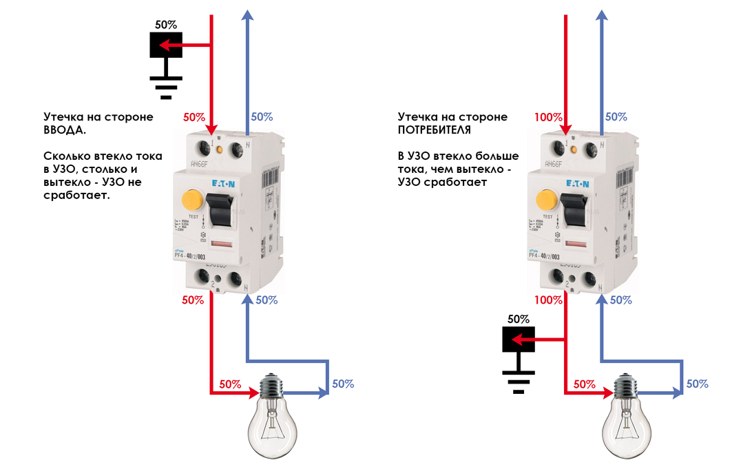
If they are not symmetrical at the output of the secondary winding of the transformer under consideration, a leakage current occurs inside the differential device, which enters the starting element, which immediately opens the power contacts of the differential current machine.
An electromagnetic release is a specialized magnet with a core that acts on the opening mechanism. The specified magnet is triggered if the load current reaches the threshold (in particular, in the event of a short circuit). The electromagnetic release is activated almost instantly - in a fraction of a second.
The thermal release is designed to protect the electrical network from current overloads. Structurally, the thermal release is a bimetallic plate, which is distinguished by its efficiency in such modes. In this case, the release mechanism is triggered by bending the plate as a result of the passage of increased currents through it. The operation of the thermal release does not occur instantly, but with a delay of some time, and the time of its operation is directly depends on the size the load current passing through the difavtomat, as well as on the ambient temperature.
Mounting
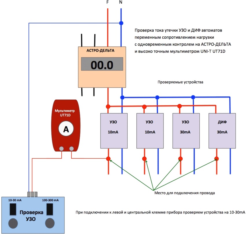
Once a month it is recommended to check the differential machine for operability. To do this, his device has a “test” button connected in series with resistance. When pressed, it supply voltage to special contact. If the difavtomat is working, then in this case it should turn off.
Important! If your device has successfully passed such a test, then you can only be sure that the integrity of the circuit is not broken.But this does not give you a guarantee that the trip leakage current and the operating speed of the differential machine meet the proper requirements.
Among other things, a residual current circuit breaker can successfully pass a “test” test, but at the same time it will ignore the real leakage of electricity due to its incorrect installation in the network.
Manufacturers of differential machines
In addition to the concept of what it is, a dif-machine, you need to have elementary knowledge about the manufacturers of these devices, the most popular of which in the world market are ABB, LeGrand, Schneider Electric and Siemens. Among domestic manufacturers, KEAZ, IEK and DEK raft can be distinguished.
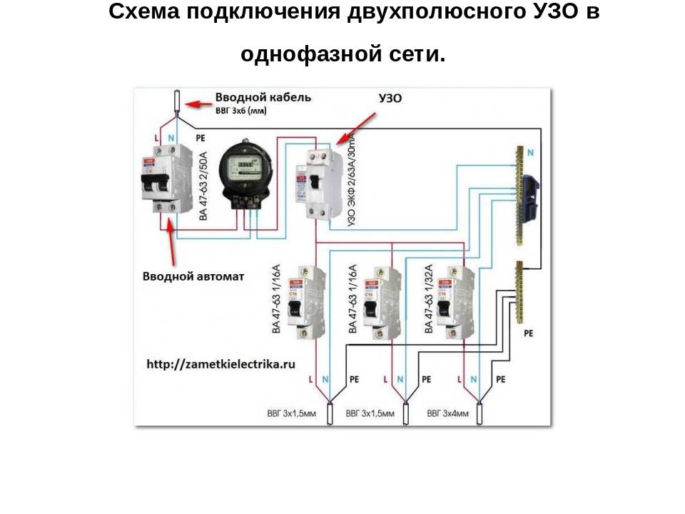
Wiring diagrams
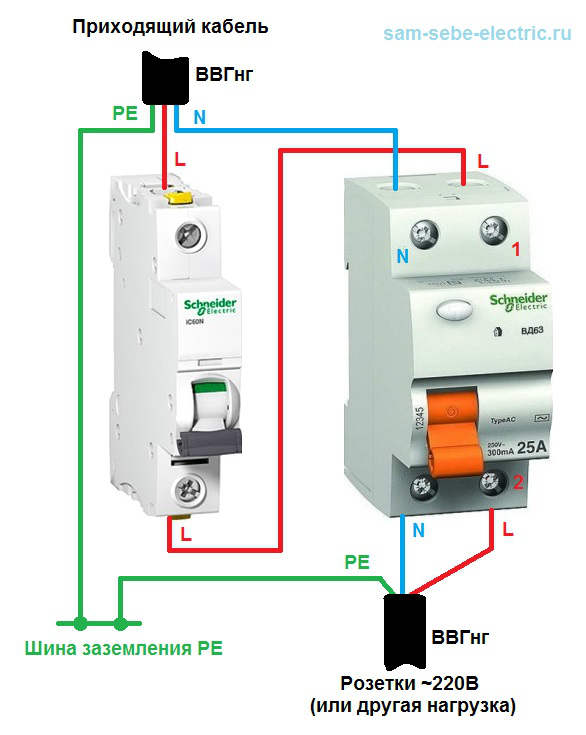
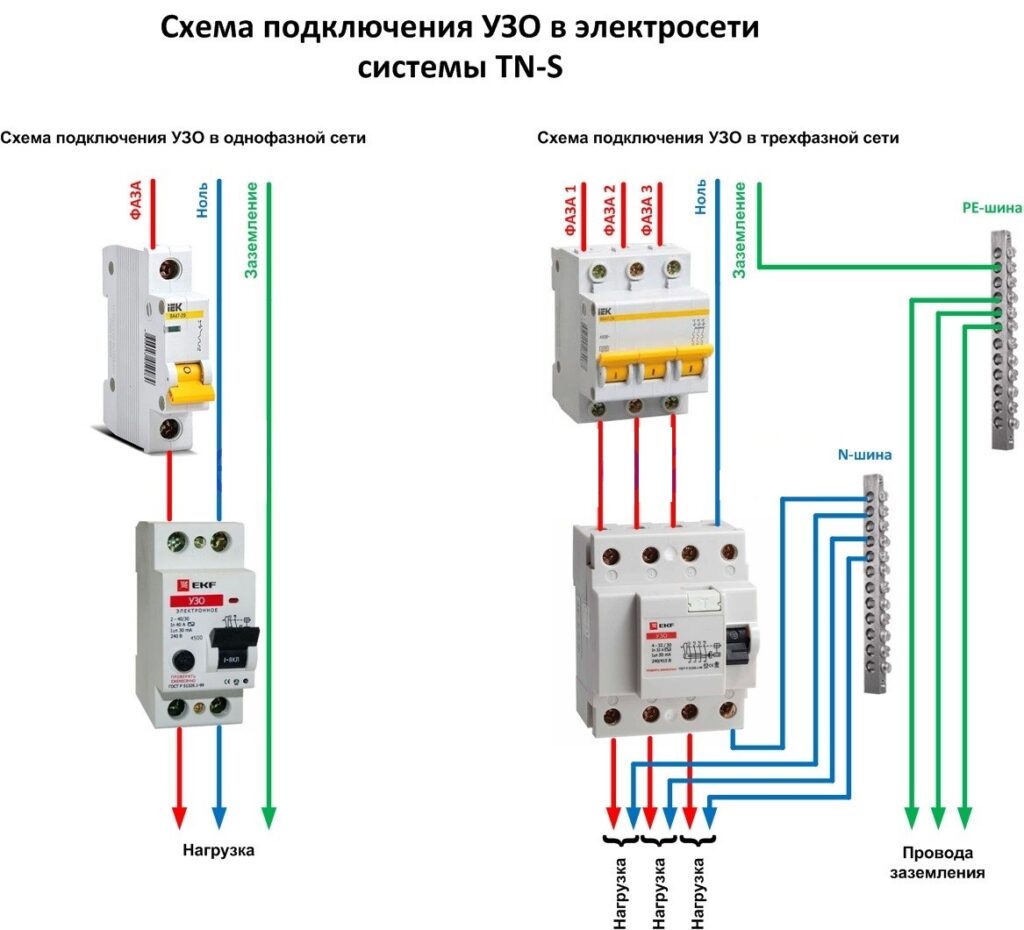
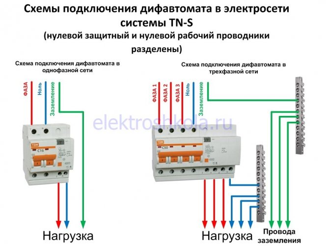
The difavtomat connection diagram is easy to read even for an inexperienced electrical engineer. Basically, it differs little from wiring diagrams for other devicesinstalled in the switchboard. Therefore, the main rule for them is exactly the same: the differential machine can be connected to the phase wires and zero only of the line (branch) that it protects.
Connect the neutral wire to the "N" terminal!

Connecting a diffuser with grounding
Introductory machine
Consider two main schemes for connecting differential automata. The first of these is sometimes called the "introductory machine", since in this case the device is placed in a shield on the input cable and all electrical circuits and groups in the network are simultaneously protected.
The residual current circuit breaker for such a circuit must be selected individually, taking into account the power consumption and other operating parameters of the network. Among the advantages of this method of organizing protection are:
- lower cost of one difavtomat;
- compactness (one device will always fit in the shield).
And the following disadvantages:
- when reacting to a malfunction, the power supply to the entire apartment is turned off;
- the repair will take longer, since it is not known for sure on which of the circuits the breakdown occurred, even the reason for the shutdown (short circuit, current leakage) is unknown.
Separate machine
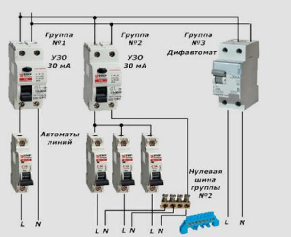
The second scheme can be called "separate automata". In this case, an automatic differential switch is placed in front of each group of consumers or a branch of the network, as well as in front of a group of difavtomatov themselves. For example, separate difautomats are installed on a lighting group, sockets and a washing machine. This is the safest way to organize the protection of the power grid and its users.

Connecting two difavtomatov
When installing such a circuit it is required to choose a common differential switch with higher operating parameters than for group machines. So, for example, if individual differential automata are designed for a current leakage of 30mA, then for the general one this parameter should be at least 100mA. If these automata are the same, then with each conflict of a separate circuit, both the group and the main circuit will work, which will lead to the shutdown of the entire network. There is another way to organize their work - to install a selective type machine (it should have the designation “S” on it). The operation of such a device occurs with a slight delay, with the help of which it is possible to organize the process of sequential shutdown of the machines.


- the highest level of security;
- at the time of disconnection, it is known exactly which of the power lines the accident occurred on.
- high cost of a set of difavtomatov;
- the design takes up a lot of space in the power shield;
- the relative difficulty of editing and reading.
A lightweight version of the previous circuit is also known, in which, for the purpose of economy, a common differential switch is not installed. In terms of functionality, this method practically does not differ from the previous one.
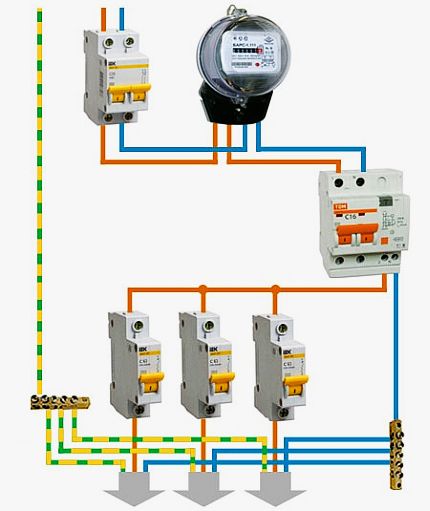
In all the above diagrams, the designation of cables is made according to the following principle: blue lines are neutral wires, red lines are phases, and yellow dotted lines are grounding.
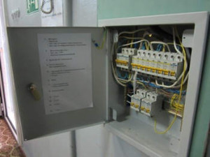
Where to install?
As a rule, the protective device is installed in the electrical panel, which is located on the landing or in a tenant's apartment. It contains many devices that are responsible for metering and distributing electricity up to a thousand watts. Therefore, in the same shield with the RCD there are automatic machines, an electric meter, clamping blocks and other devices.
If you already have a shield installed, then installing the RCD will be easy. To do this, you need only a minimal set of tools, which includes pliers, wire cutters, screwdrivers and a marker.
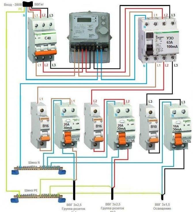
The process of installing automation in an electrical panel: step by step instructions
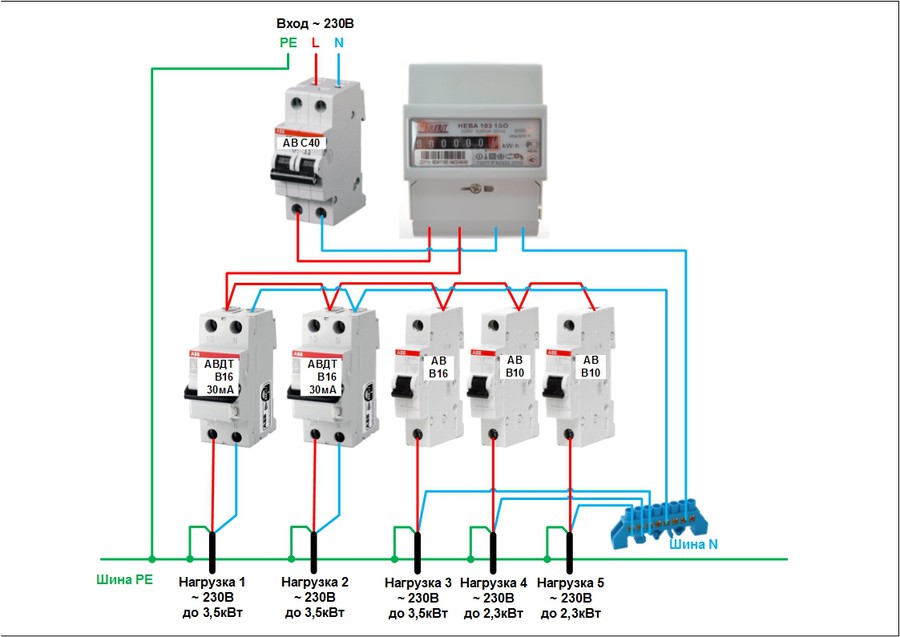
Consider the option of assembling an electrical panel for a one-room apartment, a knife switch, a protective multifunctional device will be used here, then an RCD group will be installed (type “A” for washing machine and dishwasher, because such a device is recommended by the manufacturer of the equipment). After the protective device, all groups of automatic switches will go (for air conditioning, refrigerator, washing machine, dishwasher, stove, as well as for lighting). In addition, impulse relays will be used here, they are needed to control lighting fixtures.A special module for electrical wiring will still be installed in the shield, which resembles a junction box.
Step 1: first, you need to place all the automation on the DIN rail, in the way we will connect it.
This is how the devices will be located in the shield
In the shield, first there is a knife switch, then an UZM, four UZOs, a group circuit breakers according to 16 A, 20 A, 32 A. Next, there are 5 impulse relays, 3 lighting groups of 10 A each and a module for connecting wiring.
Step 2: Next, we need a two-pole comb (in order to power the RCD). If the comb is longer than the number of RCDs (in our case, four), then it should be shortened using a special machine.
We cut the comb to the desired size, and then set the limiters along the edges
Step 3: Now for all RCDs, power should be combined by installing a comb. Moreover, the screws of the first RCD should not be tightened. Next, you need to take cable segments of 10 square millimeters, remove the insulation from the ends, crimp with tips, and then connect the knife switch to the UZM, and the UZM to the first UZO.
This is what the connections will look like
Step 4: next, you need to supply power to the circuit breaker, and, accordingly, to the RCD with RCD. This can be done using a power cable that has a plug on one end and two crimped wires with lugs on the other. And first you need to insert the crimped wires into the switch, and only then make a connection to the network.
Next, it remains to connect the plug, then set the approximate range on the USM and press the "Test" button. So, it will turn out to check the performance of the device.
Here you can see that the RCD is functioning, now it is necessary to check each RCD (if connected correctly, it should turn off)
Step 5: now you need to turn off the power and continue the assembly - you should power the group of circuit breakers on the center rail with the comb. Here we will have 3 groups (the first is the hob / oven, the second is the dishwasher and washing machine, the third is the sockets).
We install the comb on the machines and transfer the rails to the shield
Step 6: Next you need to move on to zero tires. Four RCDs are installed here, but only two neutral tires are required, because they are not required for 2 groups. The reason for this is the presence of holes in the machines not only from above, but also from below, so we will connect the load to each of them, respectively, and the bus is not required here.
In this case, a cable of 6 square millimeters is required, which must be measured in place, stripped, clamped the ends and connected to the RCD with its groups.
By the same principle, it is necessary to power the devices with phase cables
Step 7: since we have already connected the automation, it remains to power the impulse relays. Should connect them between a cable of 1.5 square millimeters. In addition, the phase of the machine should be connected to the junction box.


This is what the shield will look like when assembled.
Next, you need to take a marker to put down the labels of the groups for which this or that equipment is intended. This is done in order not to get confused in case of further repairs.
Safety work with RCD and automatic
Safety rules in the process of work
Most of the rules are general in nature, that is, they must be applied in the process of any electrical work.
If you decide to equip the electrical distribution panel yourself, before how to install and connect UZO, don't forget:
- turn off the power supply - turn off the machine at the entrance;
- use wires with the appropriate color marking;
- do not use metal pipes or fittings in the apartment for grounding;
- install an automatic input switch first.
If possible, it is recommended to use separate devices for lighting lines, sockets, circuits for a washing machine, etc. Otherwise, it is sufficient to install a common RCD.
To protect children, all electrical installations from the children's room are usually combined into one circuit and equipped with a separate device. Instead of an RCD, you can use a difavtomat
In addition to the characteristics of the devices themselves, the parameters of other electrical wiring elements are also important, for example, the cross section of the electrical wire. It should be calculated taking into account the constant load.
Unite wires between each other it is better with the help of terminal blocks, and for connecting to devices - use specially designed, marked terminals, as well as a diagram on the case.


