- Water pressure reducer: purpose and principle of operation
- How to set the relay correctly?
- The device and principle of operation of the pressure switch
- Do I need a gearbox before the boiler?
- The device and principle of operation of the pressure switch
- Instrument selection criteria
- Instrument Adjustment Recommendations
- Manufacturers
- Step by step installation instructions
- Installation
- Instrument adjustment
- Tips for choosing WFD
- Advice from experienced professionals
- Criterias of choice
- Primary indicators
- Classification of controller models
- Principle of operation and design
Water pressure reducer: purpose and principle of operation
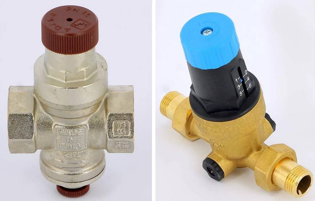
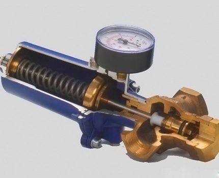
With the purpose of the water reducer, everything is more or less clear - as a rule, it is used to stabilize pressure and thus prevent the failure of some plumbing equipment. In most cases, the installation of a water pressure reducer is done when devices such as storage water heaters and thermostatic mixers are involved in the operation of a home plumbing - in general, units that are sensitive to fluid pressure. Everything is simple and clear here, which cannot be said about the principle of operation of the water pressure reducer - we will deal with it in more detail, since in this respect there are as many as three varieties of such devices.
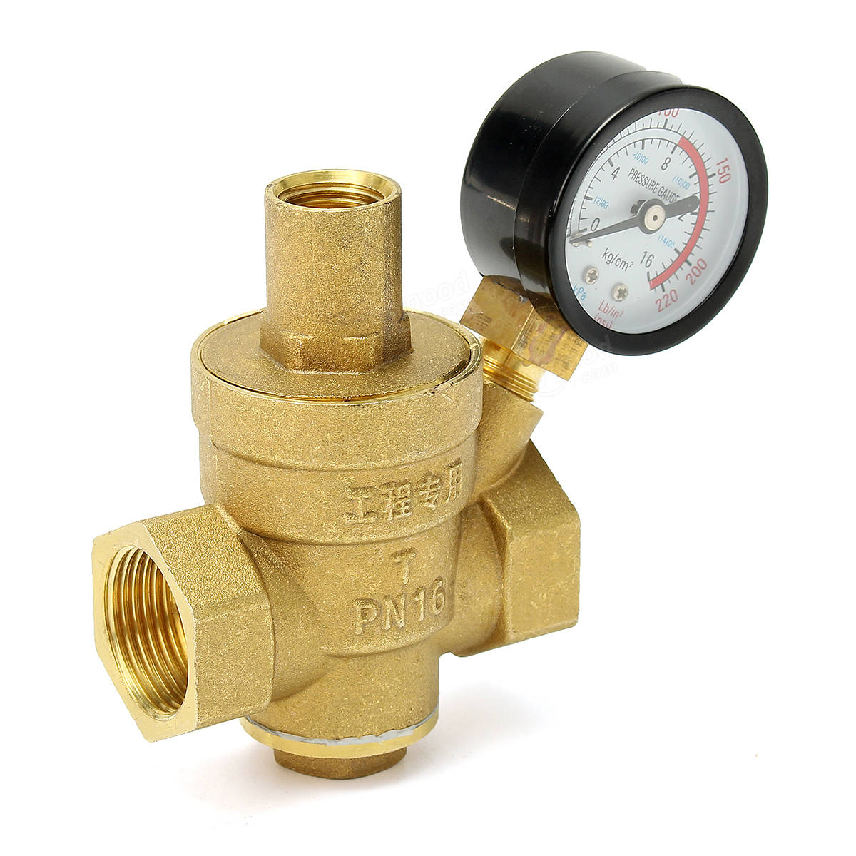
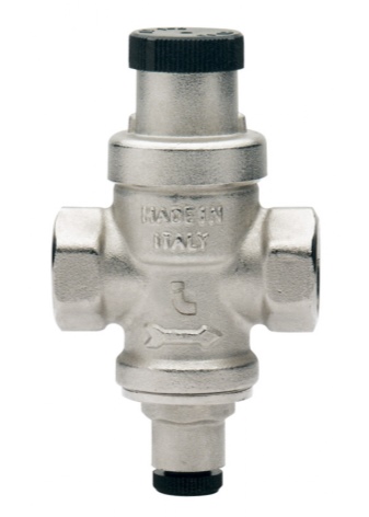
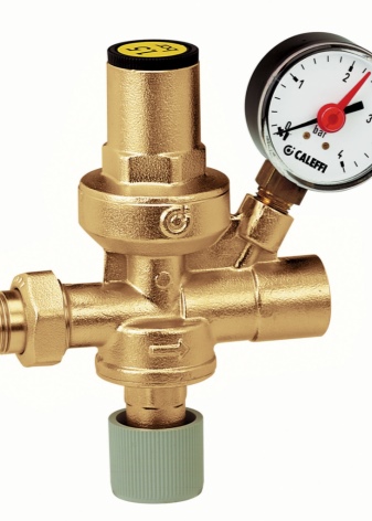
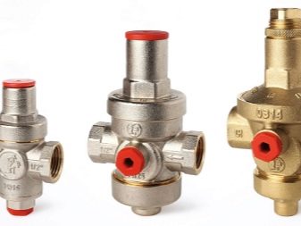
- Piston water pressure reducer - its main advantage lies in the simplicity of design. A small spring-loaded piston is responsible for regulating the pressure in the plumbing system, which, by reducing or increasing the through hole, regulates the water pressure in the system - setting the outlet pressure in such gearboxes is carried out by weakening or compressing the spring by rotating a special valve. If we talk about the shortcomings of such gearboxes, then it is necessary to highlight such a moment as the need for preliminary filtration of the liquid - without cleaning the water from debris, such devices become clogged and fail very quickly. Due to this behavior, manufacturers quite often equip such devices with a complete filter element - a piston water pressure reducer with a filter is capable of adjusting the pressure in the range from 1 to 5 atm.
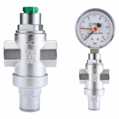
- Membrane pressure reducer. This type of gearboxes is distinguished by high reliability and unpretentiousness in operation - they stand out from all other similar devices with a wide range of throughput. As a rule, they are able to provide a working fluid flow rate ranging from 0.5 to 3 cubic meters per hour, which is quite a lot, especially when it comes to their use in everyday life. A spring-loaded membrane is responsible for the operation of such a gearbox, which, in order to prevent blockages, is placed in a separate sealed chamber - depending on the degree of compression of the spring, it exerts one or another pressure on a small valve, which reduces or increases the throughput of the device.
-
Flow reducer for reducing water pressure.Devices of this type are distinguished by the fact that they do not have any moving parts, which increases their reliability and durability - pressure reduction is achieved here due to the internal labyrinth of a mass of small ducts. Passing countless turns of these channels, splitting into several streams and again combining into one, the water velocity is extinguished, and, as a result, the pressure of the liquid at the outlet of such devices decreases. In everyday life, such devices are usually used for irrigation systems - their main disadvantage is the need to install an additional regulator at the outlet.
In general, this is all that can be said about the water pressure reducer, or rather its principle of operation, studying which we involuntarily touched on the topic of their varieties. But, as they say, this is only the beginning, and the types of these devices are not limited to this.
How to set the relay correctly?
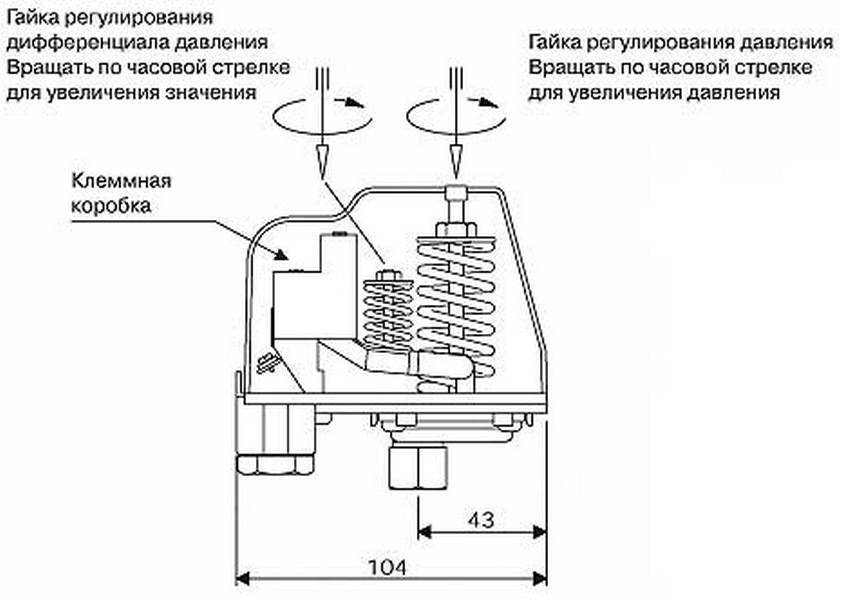
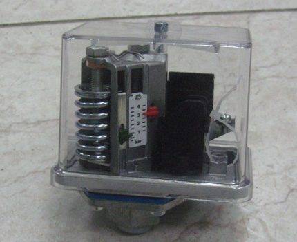
On the pressure switch housing there is a cover, and under it - two springs equipped with nuts: large and small. By rotating these springs, the lower pressure in the accumulator is set, as well as the difference between switching pressures and shutdowns. The lower pressure is regulated by a large spring, and a small one is responsible for the difference between the upper and lower pressure.
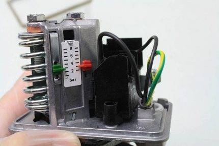
There are two adjusting springs under the cover of the pressure switch. The large spring regulates the activation of the pump, and the small spring regulates the difference between the on and off pressure.
Before starting the setup, it is necessary to study the technical documentation of the pressure switch, as well as the pumping station: the hydraulic tank and its other elements.
The documentation indicates the operating and limiting indicators for which this equipment is designed.During the adjustment, these indicators should be taken into account so as not to exceed them, otherwise these devices may soon break down.
Sometimes it happens that during setup pressure switch pressure in the system still reaches the limit values. If this happens, you just need to turn off the pump manually and continue tuning. Fortunately, such situations are extremely rare, since the power of household surface pumps is simply not enough to bring the hydraulic tank or system to its limit.
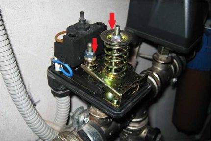
On the metal platform where the adjusting springs are located, the designations “+” and “-“ are made, which allow you to understand how to rotate the spring in order to increase or decrease the indicator
It is useless to adjust the relay if the accumulator is filled with water. In this case, not only the water pressure will be taken into account, but also the parameters of the air pressure in the tank.
To adjust the pressure switch, follow these steps:
- Set the operating air pressure in the empty accumulator.
- Turn on the pump.
- Fill the tank with water until the lower pressure is reached.
- Switch off the pump.
- Turn the small nut until the pump starts.
- Wait until the tank is full and the pump is turned off.
- Open water.
- Rotate the large spring to set the cut-in pressure.
- Turn on the pump.
- Fill the hydraulic tank with water.
- Correct the position of the small adjusting spring.
You can determine the direction of rotation of the adjusting springs by the signs “+” and “-”, which are usually located nearby. To increase the switching pressure, the large spring must be rotated clockwise, and to decrease this figure, it must be rotated counterclockwise.
The pressure switch adjusting springs are very sensitive, so they need to be tightened very carefully, constantly checking the condition of the system and the pressure gauge
Rotation of the adjusting springs during adjustment pressure switch for the pump must be performed very smoothly, about a quarter or half a turn, these are very sensitive elements. The pressure gauge should show lower pressure when switched on again.
With regard to indicators when adjusting the relay, it will be useful to remember the following points:
- If the hydraulic tank is filled, and the pressure gauge remains unchanged, it means that the maximum pressure in the tank has been reached, the pump should be turned off immediately.
- If the difference between the cut-off and turn-on pressures is about 1-2 atm, this is considered normal.
- If the difference is greater or less, the adjustment should be repeated, taking into account possible errors.
- The optimal difference between the set lower pressure and the pressure determined at the very beginning in an empty accumulator is 0.1-0.3 atm.
- In the accumulator, the air pressure should not be less than 0.8 atm.
The system can turn on and off properly in automatic mode and with other indicators. But these boundaries make it possible to minimize the wear of equipment, for example, the rubber lining of a hydraulic tank, and extend the operation time of all devices.
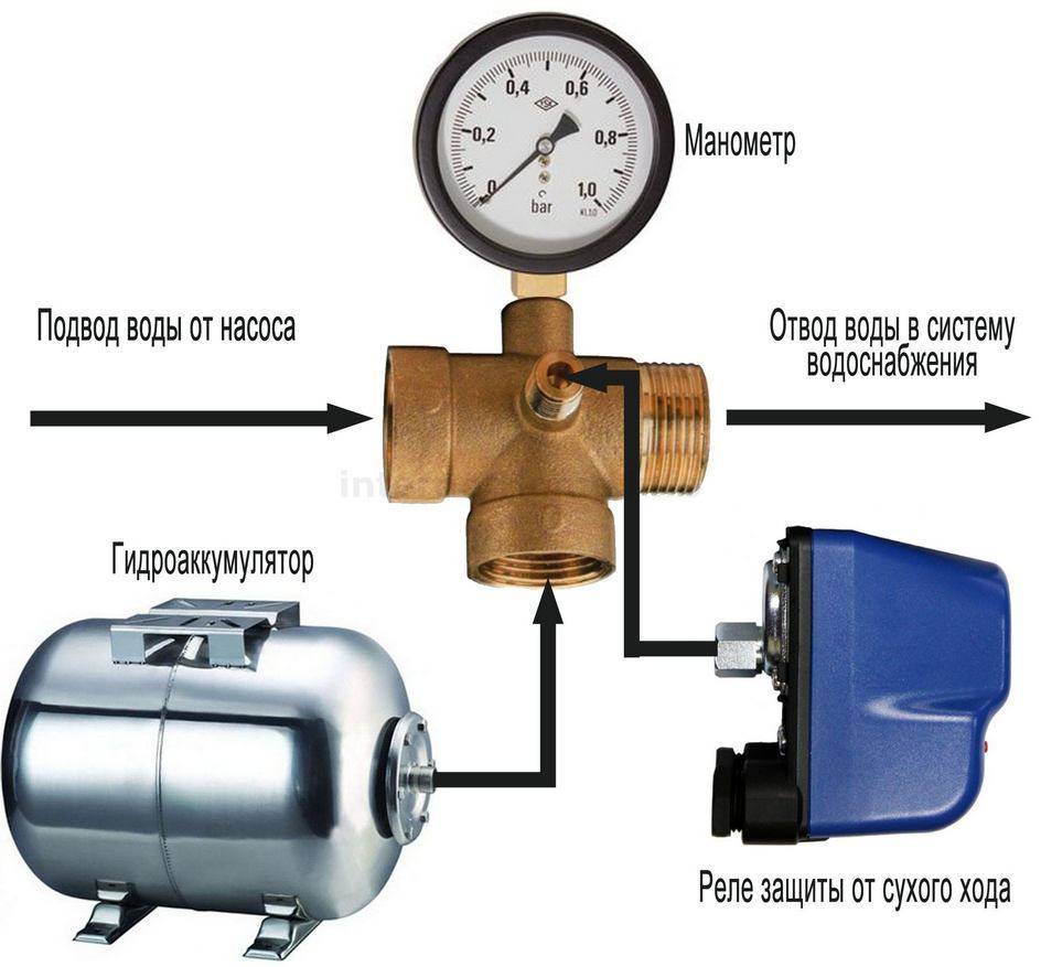
The device and principle of operation of the pressure switch
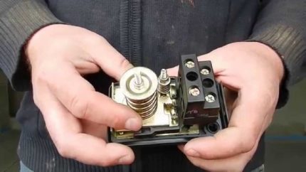
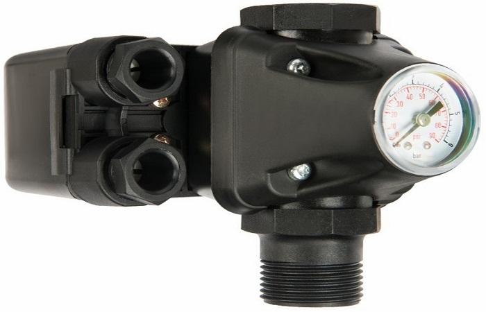
relay device pump station pressure does not differ in complexity. The design of the relay includes the following elements.
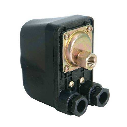
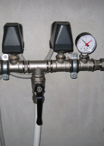
Housing (see picture below).
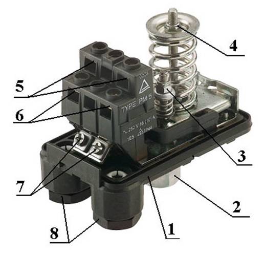
- Flange for connecting the module to the system.
- Nut designed to adjust the shutdown of the device.
- A nut that regulates the compression force in the tank at which the unit will turn on.
- Terminals to which the wires coming from the pump are connected.
- Place for connecting wires from the mains.
- Ground terminals.
- Couplings for fixing electrical cables.
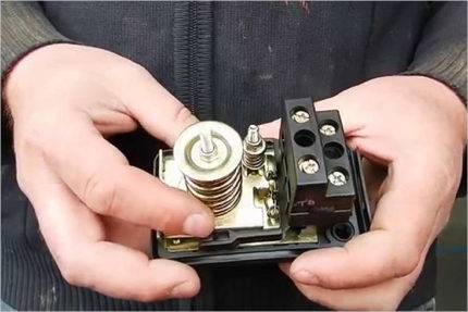
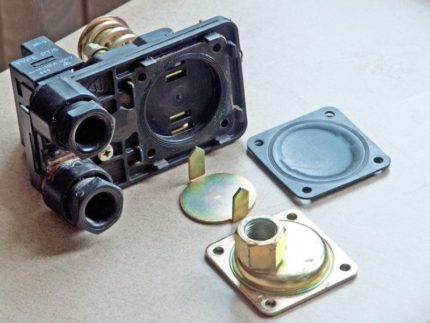
There is a metal cover on the bottom of the relay. If you open it, you can see the membrane and the piston.
The principle of operation of the pressure switch is as follows. With an increase in the compression force in the hydraulic tank chamber designed for air, the relay membrane flexes and acts on the piston. He gets in motion and engages relay contact group. The contact group, which has 2 hinges, depending on the position of the piston, either closes or opens the contacts through which the pump is powered. As a result, when the contacts are closed, the equipment is started, and when they are opened, the unit stops.


Do I need a gearbox before the boiler?
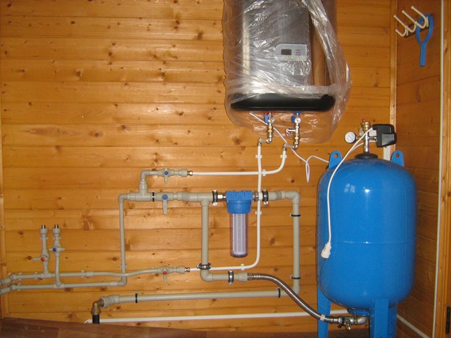
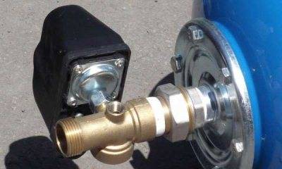
The instructions for any boiler indicate that starting a water heater without a gearbox (at the inlet) is strictly prohibited. The reason is banal - this is additional protection against excessive pressure in the water supply. The technical specifications for boilers indicate the requirements for maximum pressure in the range of 4 - 5 atmospheres. But on the lower floors of apartment buildings, from time to time it can rise to the level of up to 9 - 10 atmospheres. What will happen in this case without the installed gearbox? It is even possible to break the water heater tank. The consequences of such an emergency can be the most deplorable. In the best case - payment for the repair of a neighbor living below, in the worst case - harm to health (up to death).
Connection at the input to the boiler.In the absence of a gearbox, there is a possibility of a tank rupture
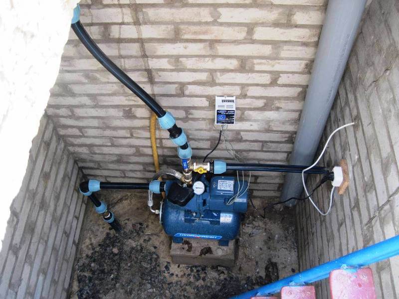
In total, the pressure reducer in the water supply system helps to regulate the water pressure, and at the same time protects the equipment from excessive pressure. It is installed at the inlet before the branching of the pipes. It is combined with a pumping pump, then the gearbox acts as a pressure-normalizing element.
The device and principle of operation of the pressure switch
Pressure switch device pumping station is not difficult. The design of the relay includes the following elements.
Housing (see picture below).

- Flange for connecting the module to the system.
- Nut designed to adjust the shutdown of the device.
- A nut that regulates the compression force in the tank at which the unit will turn on.
- Terminals to which the wires coming from the pump are connected.
- Place for connecting wires from the mains.
- Ground terminals.
- Couplings for fixing electrical cables.
There is a metal cover on the bottom of the relay. If you open it, you can see the membrane and the piston.

The principle of operation of the pressure switch is as follows. With an increase in the compression force in the hydraulic tank chamber designed for air, the relay membrane flexes and acts on the piston. It sets in motion and activates the contact group of the relay. The contact group, which has 2 hinges, depending on the position of the piston, either closes or opens the contacts through which the pump is powered. As a result, when the contacts are closed, the equipment is started, and when they are opened, the unit stops.
Instrument selection criteria
When choosing equipment that controls the strength of the water flow, you should carefully study its technical characteristics.
Particular attention should be paid to the range of operating temperature and pressure for which it is designed, the diameter of the thread and mounting holes, the protection class, the nuances of the application.
It is also important to clarify what materials the product is made of.
Experts consider devices made of brass, stainless steel, and aluminum to be the most reliable and durable. These materials protect the structure from the critical consequences of a frequent phenomenon in plumbing systems - hydraulic shocks.
Considering different modifications of the relay, it makes sense to purchase an option made of metal. The body and working components of such devices are characterized by increased strength.
This fact allows the equipment for a long time to withstand severe loads arising from significant pressure in the water supply system. on the liquid sidepassing through the sensor.
The pressure value at which the relay operates must correspond to the power of the installed pump. The parameters of the water flow circulating through the pipeline depend on this characteristic.
It is advisable to choose a device with two springs that controls the operation of the pumping station according to certain lower and upper pressure marks.
The operating temperature range of the sensor directly indicates the possible area of its application. For example, for hot water circuits and heating systems, models with a high boundary temperature are intended. For pipelines with cold water, a range of up to 60 degrees is enough


Another important criterion worth mentioning is the climatic conditions necessary for the operation of the product.This is the recommended air temperature and humidity level that the device needs to provide so that it can work with the best performance.
The maximum allowable loads for a particular device are determined by the protection class specified in the technical specifications.
When buying a flow sensor, you should check the diameter of the thread section and the dimensions of the mounting holes in the equipment: they must fit perfectly with the elements of the pipeline. The correctness and accuracy of further installation, as well as the efficiency of the relay after installation, depend on this.
Instrument Adjustment Recommendations
By manipulating the springs, you can achieve a change in the pump shutdown threshold, as well as adjust the volume of water in the hydroaccumulator tank. It is generally accepted that the larger the delta, the greater the volume of liquid in the tank. For example, with a delta of 2 atm. the tank is filled with water by 50%, at a delta of 1 atm. - by 25%.
To achieve a delta of 2 atm., It is necessary to set the lower pressure value, for example, to 1.8 atm., and the upper one to 3.8 atm., Changing the position of the small and large springs
First, let's recall the general rules of regulation:
- to increase the upper limit of operation, that is, to increase the shutdown pressure, tighten the nut on the large spring; to reduce the "ceiling" - weaken it;
- to increase the difference between the two pressure indicators, we tighten the nut on a small spring, to reduce the delta, we weaken it;
- nut movement clockwise - increase in parameters, against - decrease;
- for adjustment, it is necessary to connect a pressure gauge, which shows the initial and changed parameters;
- before starting the adjustment, it is necessary to clean the filters, fill the tank with water and make sure that all pumping equipment is working.
Manufacturers
Among the leading manufacturers of gearboxes, Italian companies predominate. They are traditionally famous among manufacturers of similar products. However, the Russian company Valtec or the American Honeywell are no less famous.
For a more visual comparison of products from different manufacturers, we will make a table:
| Brand | Pressure (max) | Temperature (max) | Setting limits (Bar) | pressure gauge | Adjustment type |
| Valtec | 16 At | 40° — 70° | 1,5-6 | There is | A pen |
| Honeywell | 25 At | 40° — 70° | 1,5-6 | There is | A pen |
| Watts | 10 At | 30° | 1-6 | There is | A pen |
| Hertz | 10 At | 40° | 1-6 | There is | A pen |
| Caleffi | 10 At | 80° | 1-6 | There is | A pen |
| Giacomini | 16 At | 130° | 1-5,5 | There is | A pen |
Looking at the table, you can see that the parameters of all household devices are more or less similar. Only the maximum temperature and operating pressure differ. This makes it easier for users to choose the right device.
Step by step installation instructions
Simplicity of design and ease of regulation allow you to perform work on embedding the device in a plumbing system without having professional skills.
Installation
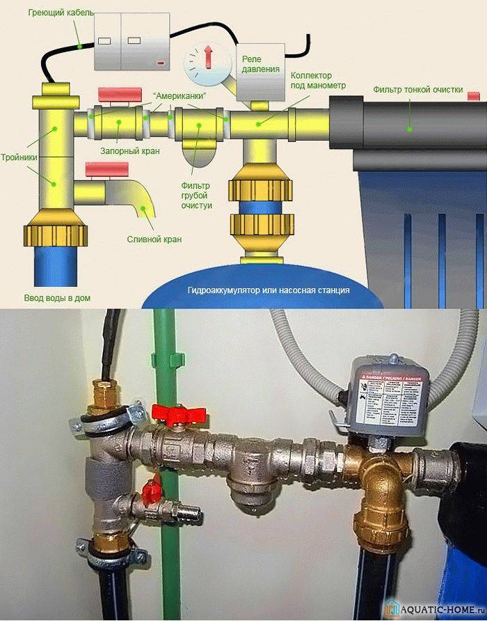
Assembly procedure:
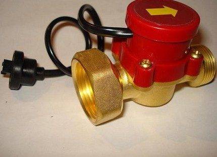
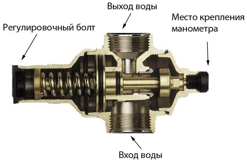
- Determine the installation position of the device. An arrow image is found on the device body and combined with the direction of the water flow in the system.
- The installation of the pressure regulator in the pipeline system is carried out with the help of two half-strings (at both ends).
The common name for this compound is "American".Usually these spare parts are included with the product, if they are not available, they are easily selected in any specialized store.
Depending on the material of the water pipes (polypropylene, metal-plastic, metal), the corresponding half-strings are bought. In some cases, the purchase of adapters is required.
In the polypropylene version of pipelines, connecting products are soldered to the ends of the pipes using a welding soldering iron. Then the regulator itself is installed by tightening the nuts of the half-wheels on both sides of the device. With a metal version of the pipeline, the connection is made using flax and sanitary sealant
To install polusgonov in this way, you will need a gas or adjustable wrench.
These same tools are used to tighten the nuts on the threaded ends of the regulator when it is connected to the plumbing system.
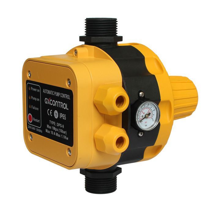
If the gearbox being installed is equipped with a pressure gauge, during installation pay attention to the visual availability of the readings on the dial of the device.
Instrument adjustment
The standard pressure in the water system is 2-4 atm, the real one is always higher. The factory preset pressure regulators correspond on average to 3 atm. For a longer service life of the gearbox, the difference in water pressure after the device should not exceed 1.5 atm in continuous operation.
To obtain the desired pressure, the gearbox is adjusted:
- with the help of shut-off valves (ball valve, valve) they shut off the water in the home plumbing system;
- using a flat or curly screwdriver, turn the adjustment screw to the desired angle;
- open the inlet tap and at the same time the valve of the sink or bath faucet, monitor the setting readings on the pressure gauge;
- the process is repeated until the desired results are achieved.
In modern models, a knob and a pressure scale are provided to adjust the pressure. Depending on the direction of turning the knob, the water flow at the outlet of the device decreases or increases.
Tips for choosing WFD
 Water pressure regulator
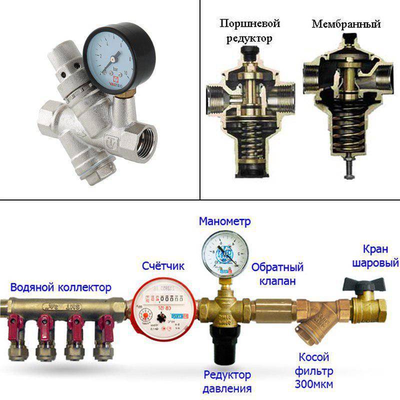
Household regulators are membrane and piston. The second of them are highly sensitive to water quality and are used only for mounting auxiliary filters. The piston may get stuck due to the penetration of dirt, as a result, the device will not work.


Membrane regulators in this regard are more reliable and are used in any water supply networks. But when using them, care must be taken to ensure that the membrane is intact when carrying out maintenance according to the manufacturer's recommendations.
When choosing a regulator, you need to pay attention to the technical parameters:
- water temperature;
- outlet pressure;
- input pressure.
The outlet pressure is selected according to the characteristics of household appliances. Most often, RFE is chosen for 4 atmospheres. To control the pressure of cold water, you should choose a regulator with an operating temperature of no more than 40 degrees, and for hot water, you can select a temperature of up to 130 degrees.
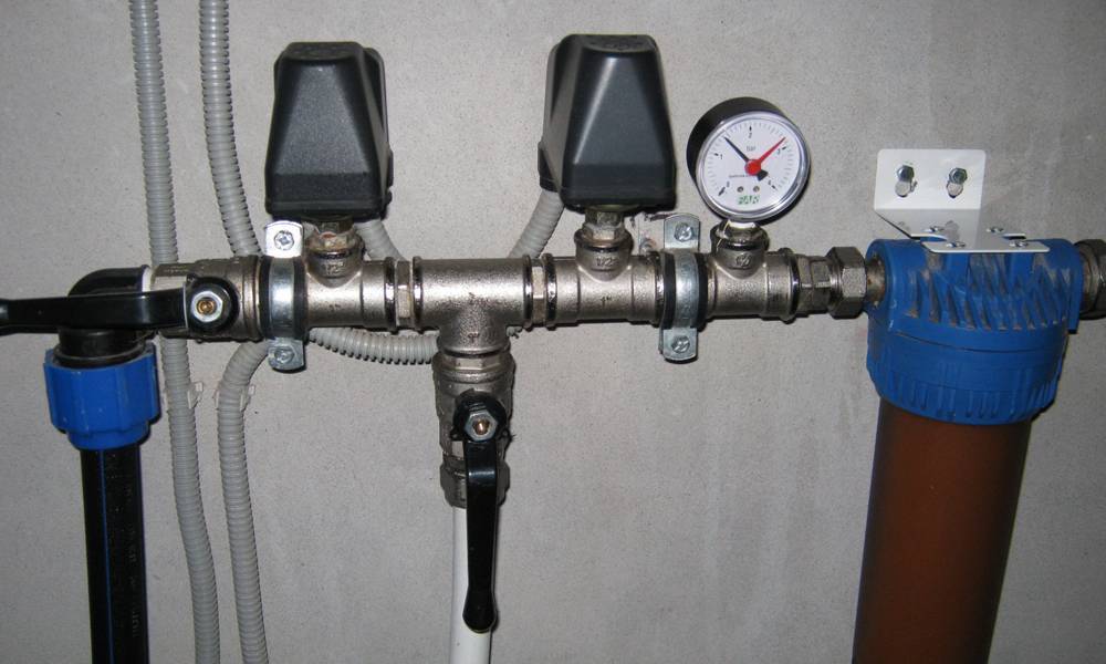
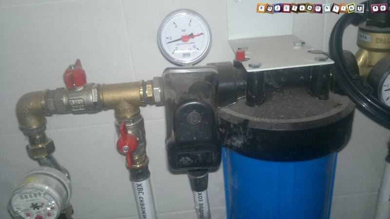
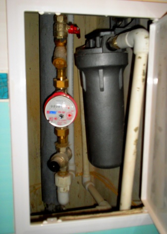
Shut-off valves are installed before and after the regulator to ensure convenient maintenance and easy access to the WFD. The regulator is installed after the place where the pipe enters the building, but before the water meters. For optimal adjustment of the operation of the RFE, it is equipped with a pressure gauge.
Advice from experienced professionals
It is recommended to connect the pressure switch of the accumulator to the electrical panel of the house through a separate line with its own RCD.
It is also mandatory to ground this sensor, for this it has special terminals.
 It is permissible to tighten the adjusting nuts on the relay until it stops, but it is highly not recommended. The device with rigidly tightened springs will work with large errors according to the set Rstart and Pstop, and will soon fail
If water is visible on the case or inside the relay, then the device should immediately be de-energized. The appearance of moisture is a direct sign of a ruptured rubber membrane. Such a unit is subject to immediate replacement, it cannot be repaired and continue to operate.
Cleaning filters in the system must be installed without fail. Nothing without them. However, they need to be cleaned regularly.
Also, once a quarter or six months, the pressure switch itself should be flushed. To do this, the cover with the inlet pipe from below is unscrewed on the device. Next, the opened cavity and the membrane located there are washed.
 The main reason for breakdowns of the accumulator relay is the appearance of air, sand or other contaminants in the pipes. There is a rupture of the rubber membrane, and as a result, the device must be replaced
Checking the pressure switch for correct operation and general serviceability should be done every 3-6 months. At the same time, the air pressure in the accumulator is also checked.
If, during adjustment, sharp jumps of the arrow on the pressure gauge occur, then this is a direct sign of a breakdown of the relay, pump or hydraulic accumulator. It is necessary to turn off the entire system and start its full check.
Criterias of choice
There are many types of controllers currently available. water pressure for apartments and private houses, but their quality does not always meet the declared.Therefore, you need to know some criteria for choosing devices to protect hydraulic equipment from high pressure and water hammer.
The body of the instruments is made of expensive materials such as stainless steel, brass and bronze. It is recommended to take several regulators and compare their weight. It is necessary to choose the device that is heavier and without sagging with burrs
You need to pay special attention to the connecting seams. Low-quality regulators are often sprayed
When choosing the best option for the regulator, it is necessary to take into account such parameters as throughput - water consumption per hour (in m3) and the unit of account, which makes it possible to reduce the pressure in the system. Local resistance formed on the site, slightly affects the operation of the entire water supply system. The adjustable regulator depends on the sensitivity of the membrane, and its quality depends on the degree of compression of the spring and the material of manufacture. If there is only one spring, the tuning limit will be one. If the manufacturer has provided several springs that differ in the degree of rigidity, the device will more accurately respond to any changes in environmental conditions.


Normally, during operation, the reducer generates noise due to cavitation, which occurs due to an increase in the head velocity when entering the device. If the flow area is too narrow, then the likelihood of cavitation is very high. Therefore, when choosing a regulator, it is necessary to know the degree of cavitation and the regulated flow rate. These values can be viewed in the device passport.
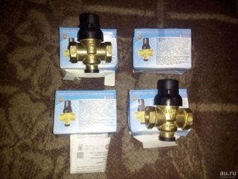
When buying a pressure regulator, it is not recommended:
- Buy a device in the market, where all spare parts are laid out on improvised flooring. This means that the equipment is counterfeit and quite inexpensive.
- Complete with the product must be a passport and a certificate of quality. Otherwise, you should refrain from purchasing a dubious device.
- Acquire a device that is designed for other operating conditions.
Primary indicators
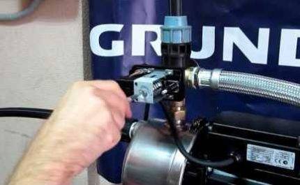
 The block is immediately hung on the pump. For a submersible pump, you need to choose it yourself. But in any case, the block is already adjusted during manufacture.
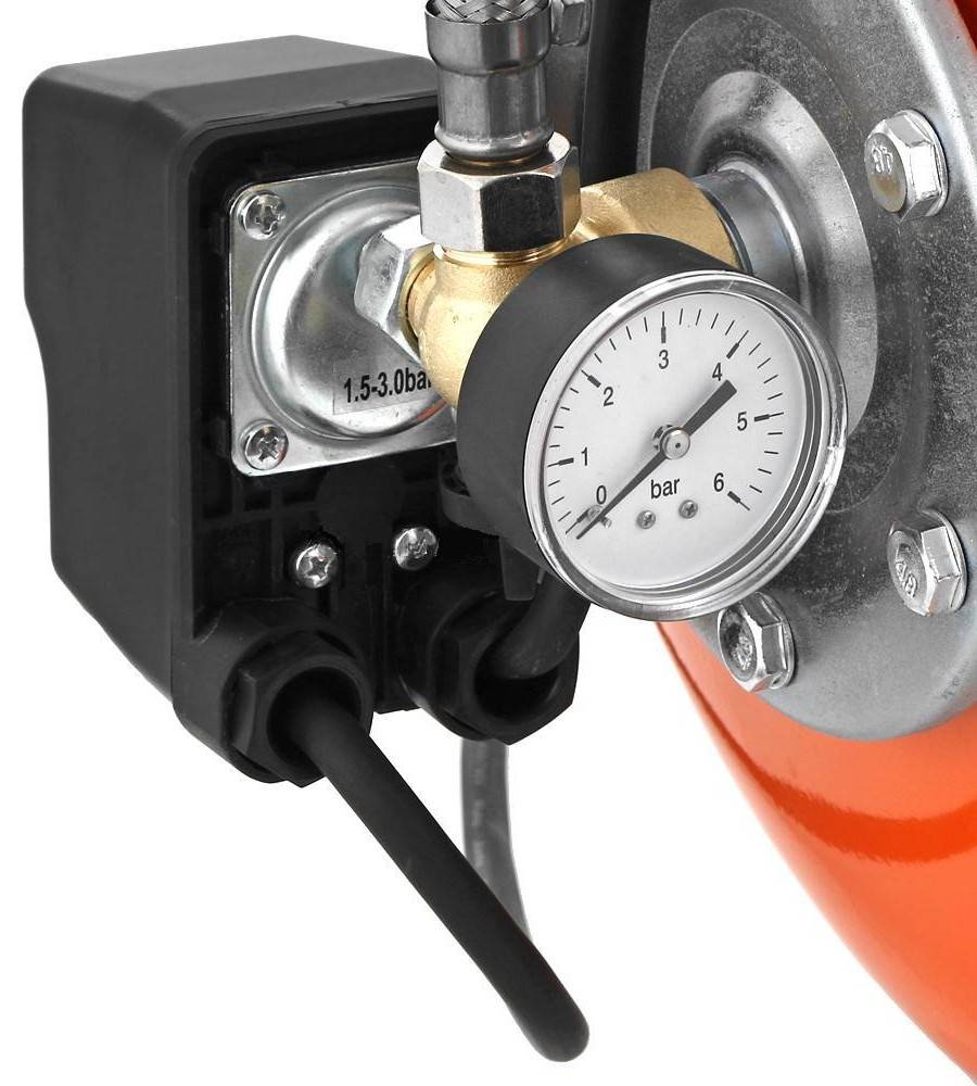
Many of them have the following start and stop settings: 1.5 - 3.0 atmospheres. But some models may have smaller values.
The lower start limit is at least 1.0 bar, the upper stop limit is 1.2 - 1.5 bar more. In the station manual, the lower start-up setting may be referred to as P, or PH.
This value may change. The difference between the lower and upper limits of operation can be referred to as ΔР (deltaР). This indicator is also regulated.
Classification of controller models
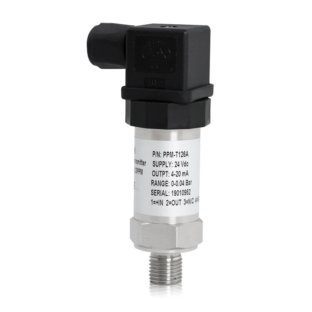
The market for equipment and spare parts for water supply systems is replete with offers from domestic and foreign factories. Among pressure sensors, you can find both inexpensive and simple models of Russian manufacturers, as well as expensive multifunctional solutions.
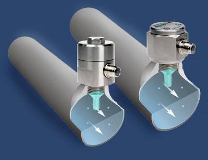
All types of sensors can be divided into 2 main groups:
- electromechanical;
- electronic.
The first type of devices has a metal plate that reacts to the pressure of the hydraulic tank membrane in the system by closing or opening contacts. If its value is insufficient, then the pump is turned on, otherwise it is turned off.
The electronic type of sensors sends a signal about the deformation of the membrane to the automatic control system. The received information is analyzed, a command is received to turn off / turn on the pump.
Such equipment is very sensitive to the slightest deviation from the set values, has protection against "dry" running. Depending on the model, it is possible to automatically start the system after an emergency shutdown, notify the owner of problems by sending a message to a mobile phone, and other additional functions.
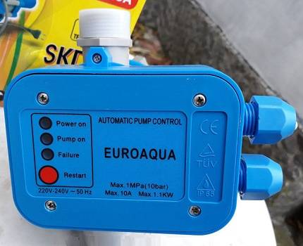
For example, the Spanish regulator KIT 02, which acts as a pressure sensor, able to maintain a constant pressure of a given value, protects against dry running, has a backstop valve, a built-in pressure gauge, and dampens water hammer. But the cost of this model is far from 1000 rubles.
Most popular device options water pressure in a private water supply system:
- Russian - RDM-5 from Gileks;
- German - Grundfos FF 4-4, Tival FF 4-4, Condor MDR 5/5;
- Italian - PM / 5G, PM / 3W from ITALTECNICA, EASY SMALL from Pedrollo;
- Spanish - electronic regulator KIT 00, 01.02, 05 from ESPA.
One of the budget solutions can be a sensor from the company Gileks RDM-5. It has factory settings for lower and upper limits of 1.4 and 2.8 atmospheres, respectively. You can change the range yourself, given that the operating values of this device are from 1.0 to 4.6 atmospheres.
The device of the German company Grundfos model FF4-4 is distinguished by the ability to set settings with an accuracy of 0.01 atm. Its operating range is from 0.07 to 4 atmospheres, and FF4-8 is up to 8 atm. It has a transparent cover and a special scale inside the device.


All this greatly simplifies self-adjustment - no need to turn the nuts and wonder if it's enough. The scale shows the result immediately. The main negative quality of the device is the cost, which is almost 5 times higher than the RDM-5.
Principle of operation and design
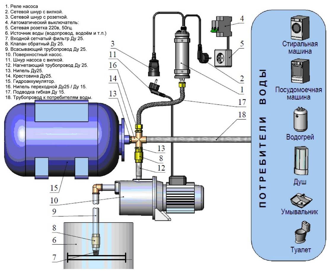
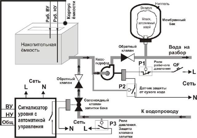
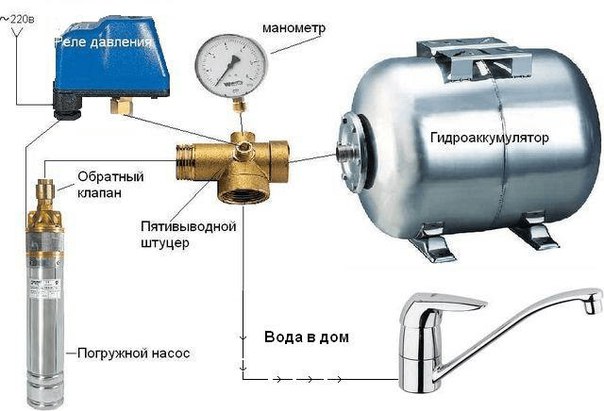
The water supply of a country house is usually carried out from a well into which an electric pump is placed to pump water. With manual control, in each case of turning on the water tap, it is necessary to turn on the electric pump.
In more complex systems, a hydraulic accumulator is used, with the help of which a constant water pressure is maintained. In order to automatically turn on and off the electric pump, a pressure sensor (switch) is used.
This relay is a device that closes contacts when the pressure in the water supply drops below a predetermined minimum threshold and opens contacts when the pressure exceeds the maximum threshold.
Structurally, the sensor is a sealed unit connected to the water supply using a small section pipe. The design of the device includes a diaphragm that reacts to fluid pressure and springs that determine relay actuation times. The thresholds are adjusted using special nuts that tighten or loosen the springs.
Typically, such a sensor has two adjusting springs of different diameters. A large diameter spring controls pressure levels. The small diameter spring is designed for differential pressure adjustment.
With an increase in water pressure, the membrane begins to move, overcomes the resistance of the spring and opens the contacts. The electric pump is switched off.When the pressure drops, the membrane moves to the other side and closes the contacts, which leads to the activation of the electric pump.
As a rule, the response thresholds of sensors of various designs can vary from 1 to 7 bar. At the same time, the factory setting of such sensors for the minimum threshold is one and a half bar, and for the maximum - about 3 bar.