- Design and principle of operation of the sensor
- Devices for natural draft boilers
- Turbine boiler sensor designs
- Flame ionization sensor
- The device of the gas boiler AOGV - 17.3-3
- Traction control functions
- Functionality check
- The principle of operation of automation on old-style gas boilers
- Replacing the thermocouple yourself in a gas stove
- Design and principle of operation
- Health check
- The principle of operation of the sensor
- Diagnosis of problems and ways to solve them
- Briefly about the three-way valve mechanism
- Conclusions and useful video on the topic
Design and principle of operation of the sensor
Given the variety of designs of gas boilers, it should be noted that draft control sensors are also found in different designs. If we consider their design only in a generalized way, we will talk about a fairly simple mechanism of devices.
The basis of almost any sensor for controlling the draft of a gas boiler is a bimetallic element that changes shape with changes in the temperature background. In fact, this is a simple bimetallic plate that bends when heated or cooled.
The change in the shape of the plate is controlled by the contact group, which transfers the state of the contacts to "on" or "off".The switching signal of the contact group is transmitted to the gas boiler controller or to a simpler gas supply control mechanism.
The type of sensor that controls the draft in the flue depends on the boiler used.
So, there are two types of gas boilers that exist and are used in practice:
- Structures equipped with a simple chimney (with natural draft).
- Structures equipped with a chimney with a turbine (with forced draft).
These designs differ from each other and the thrust sensors used for them also differ.
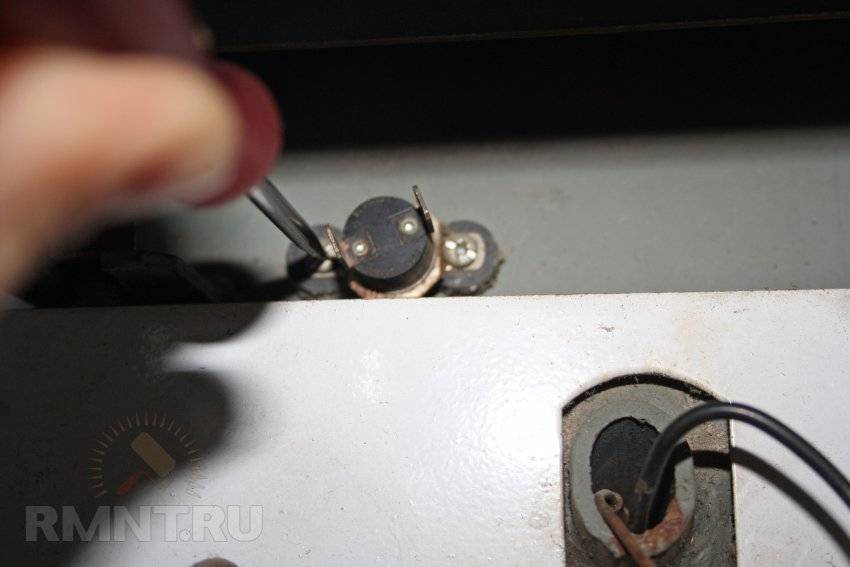
Devices for natural draft boilers
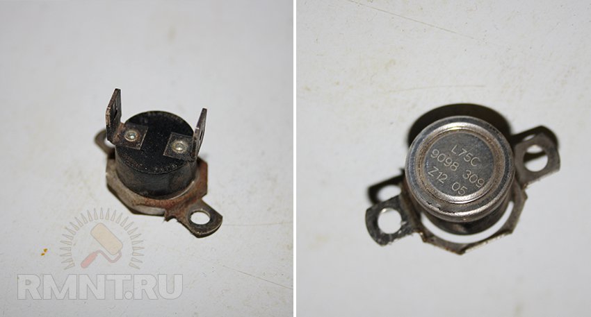
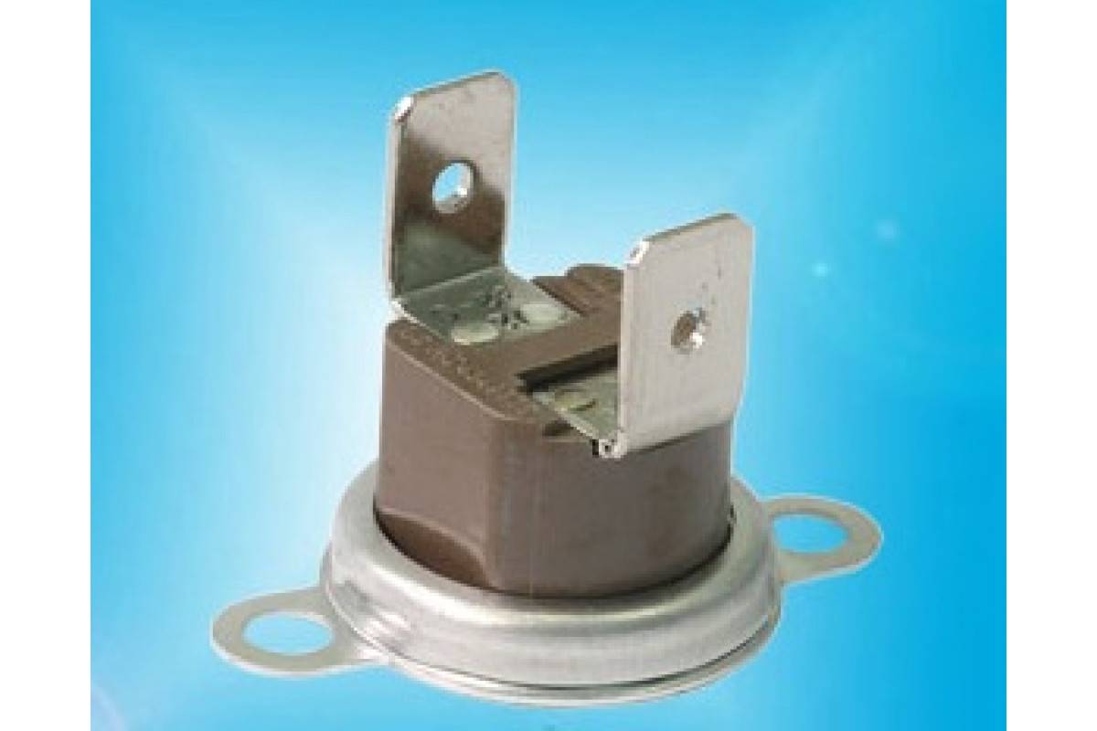
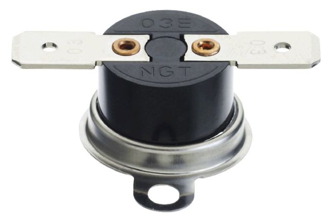
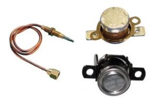
In natural draft boilers, a so-called flue gas bell is used, in the body of which a simple miniature thermostat is built in, as shown in the picture below.
A thermostat of a simple design in a miniature version is usually endowed with a corresponding temperature mark directly on the body (on a metal shell). This label (for example, 75º) indicates the temperature limit of the sensor's contact group.
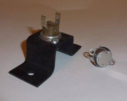 A thermostatic device of this design is installed, as a rule, as part of the structures of mounted gas boilers, where a flue gas cap is used, built into the chimney line
Such a device operates simply. If the flue gases passing through the hood with the installed sensor heat the device above the set temperature parameter (which indicates a violation of the draft mode), the contacts will open the circuit.
Accordingly, due to an open circuit, the gas supply system to the boiler will be switched off (blocked). The equipment will restart only after the sensor cools down and the open contact is restored.
Turbine boiler sensor designs
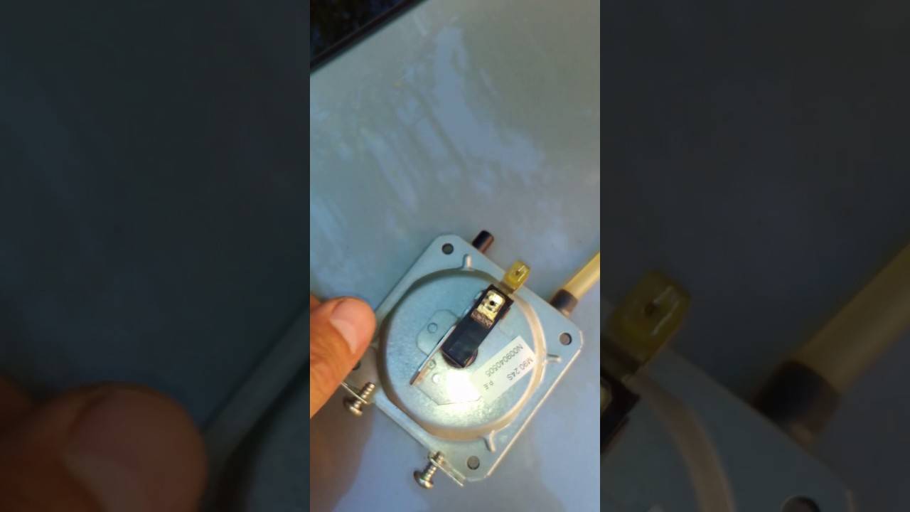
Boilers equipped with a chimney with a turbine have a slightly different sensor for determining the draft of a gas boiler with a functional principle that differs. First of all, the difference is that the sensor actually controls the boiler turbine fan. In other words, the control of the optimal flue gas draft by the fan is carried out.
That is why the device of thrust sensors for turbine gas boilers is made not under temperature control, but under control of the volume of passing carbon monoxide gases.
Such sensors work on the fact that there is an optimal vacuum inside the combustion chamber, they have a contact group of three elements:
- contact COM;
- normally open (NO);
- normally closed (NC).
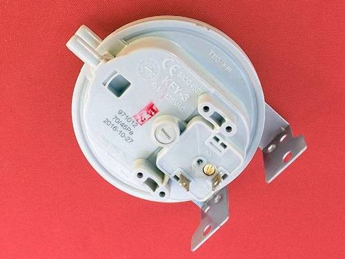
Structurally, the devices are made different in shape, but their principle of operation remains the same. Upon the formation of working conditions inside the chamber of the gas boiler (optimal vacuum), the contact group closes with the supplied air pressure, sending a signal to supply gas.
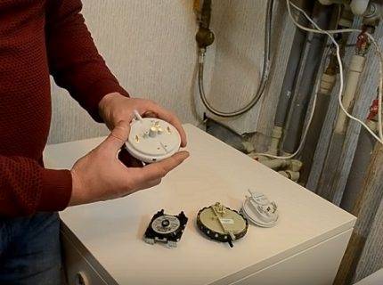 A slightly different type of sensor elements designed to control the draft in the boiler - designs, the principle of operation of which is based on the pressure difference of the outgoing flow
Flame ionization sensor
The flame ionization sensor is another device that ensures the safe operation of the boiler. Such a device monitors the presence of a flame. If during operation the sensor detects the absence of fire, then it can turn off the boiler.
The presence of a flame is controlled either by an ionization electrode or by a photosensor.
The principle of operation of such a device is based on the formation of ions and electrons during the combustion of a flame. Ions, being attracted to the ionization electrode, cause the formation of an ion current. This device is connected to a flame control sensor.


When the sensor test detects the formation of a sufficient amount of ions, the gas boiler is working normally. If the level of ions decreases, the sensor blocks the operation of the device.
In certain places, pressure gauges are connected to the air path of the igniter. The ionization electrode itself is mounted on the body of the igniter through a special sleeve, and connected to the output of the igniter machine.
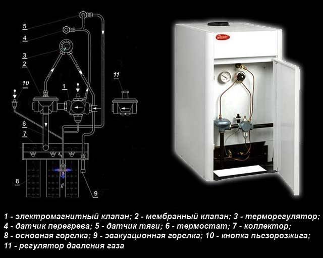
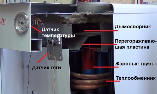
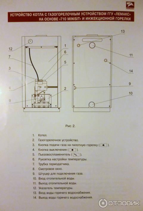
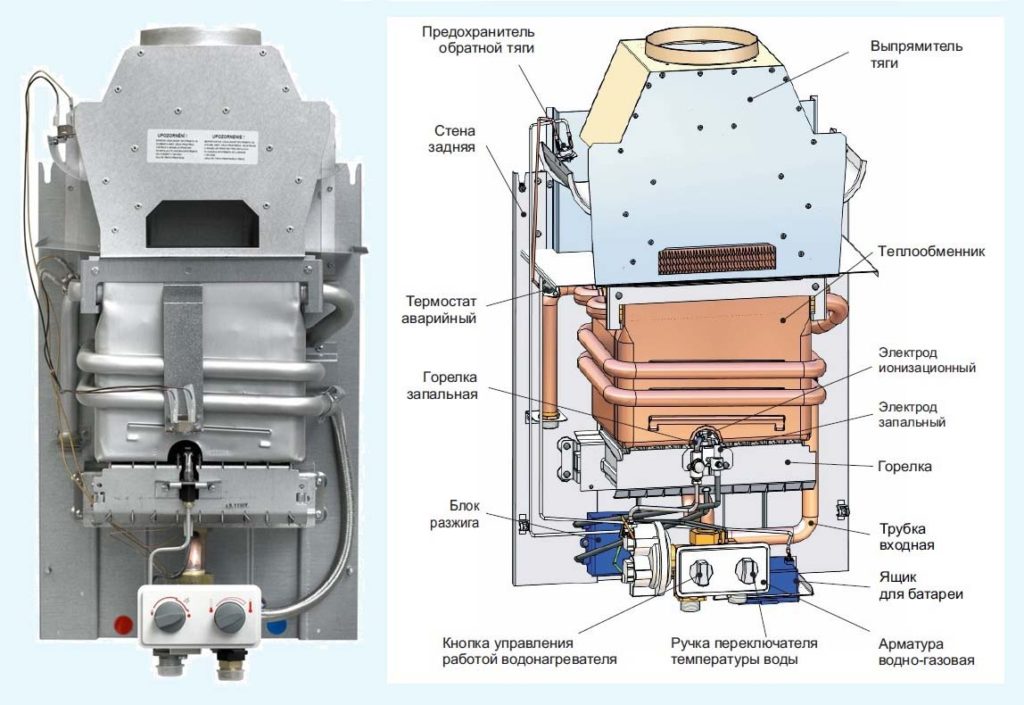
The device of the gas boiler AOGV - 17.3-3
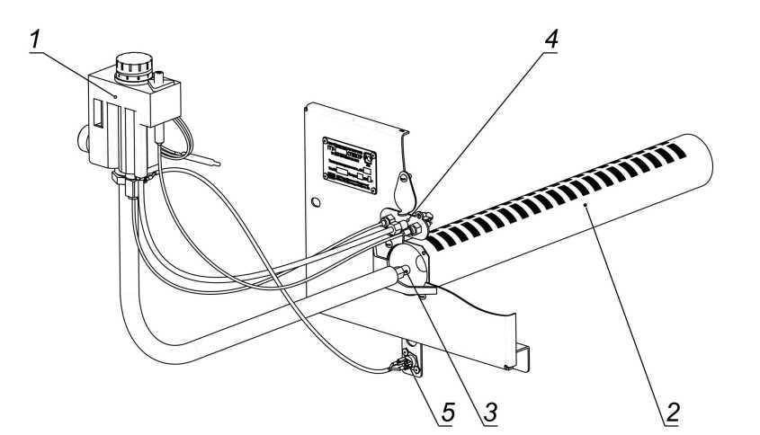
Its main elements are shown in rice. 2
. The numbers in the figure indicate: 1- traction chopper; 2- thrust sensor; 3- draft sensor wire; 4- start button; 5- door; 6- gas magnetic valve; 7- adjusting nut; 8-tap; 9-storage tank; 10-burner; 11-thermocouple; 12- igniter; 13- thermostat; 14-base; 15- water supply pipe; 16- heat exchanger; 17-turbulator; 18- knot-bellows; 19- water drainage pipe; 20- the door of the traction control; 21-thermometer; 22-filter; 23-cap.
The boiler is made in the form of a cylindrical tank. On the front side are the controls, which are covered with a protective cover. gas valve 6 (Fig. 2)
consists of an electromagnet and a valve. The valve is used to control the gas supply to the igniter and burner. In the event of an emergency, the valve automatically turns off the gas. Traction chopper 1 serves to automatically maintain the vacuum value in the boiler furnace when measuring the draft in the chimney. For normal operation, the door 20 should freely, without jamming, rotate on the axis. thermostat 13 designed to maintain a constant temperature of the water in the tank.
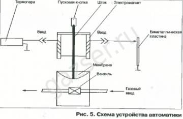
The automation device is shown in rice. 3
. Let us dwell in more detail on the meaning of its elements. Gas passing through the purification filter 2, 9 (Fig. 3)
goes to the solenoid gas valve 1. To the valve with union nuts 3, 5 draft temperature sensors are connected. The ignition of the igniter is carried out when the start button is pressed 4. There is a setting scale on the body of the thermostat 6 9. Its divisions are graduated in degrees Celsius.
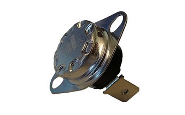
The value of the desired water temperature in the boiler is set by the user using the adjusting nut 10. Rotation of the nut leads to linear movement of the bellows 11 and stem 7. The thermostat consists of a bellows-thermobalon assembly installed inside the tank, as well as a system of levers and a valve located in the thermostat housing. When the water is heated to the temperature indicated on the adjuster, the thermostat is activated, and the gas supply to the burner stops, while the igniter continues to work. When the water in the boiler cools down 10 … 15 degrees, the gas supply will resume. The burner is ignited by the flame of the igniter. During operation of the boiler, it is strictly forbidden to regulate (reduce) the temperature with a nut 10 - this can lead to breakage of the bellows. You can reduce the temperature on the adjuster only after the water in the tank has cooled down to 30 degrees. It is forbidden to set the temperature on the sensor above 90 degrees - this will trigger the automation device and turn off the gas supply. The appearance of the thermostat is shown in (Fig. 4)
Traction control functions
The main task will become clear if you look at the name of the device. If you do not regulate the temperature of the coolant (water jacket), it will simply boil.Without an automatic regulator, you will either have to constantly add liquid, or manually control the flow of air entering the furnace.
The traction regulator greatly facilitates the life of the owners of a private house. In addition to controlling, it performs two more useful functions:
- setting and maintaining the maximum allowable water temperature without boiling (up to 90 ° C; this is especially true in autumn or early spring);
- fuel economy (when the damper is closed, the intensity (speed) of burning firewood decreases (albeit due to a decrease in the efficiency of the boiler)).
Installing a draft regulator on a solid fuel boiler involves certain costs. In order to save money, some use a safety valve for similar purposes. For some reason, it is considered an analogue of the regulator.
The solution is not the most rational, because after 3-4 operations (shutdown of the boiler at the risk of overheating and reactivation in case of excessive cooling), the accessory starts to leak.
Functionality check
All of the above can be summarized into one: the sensor is necessary in order to shut off the fuel supply in the event of a danger - such as a gas leak or poor removal of combustion products. If this is not done, very sad consequences are possible.
About carbon monoxide poisoning has already been mentioned more than once above. It very often leads to death, and you definitely shouldn’t joke with it. And in the event that the burner suddenly goes out, but the gas continues to flow, sooner or later an explosion will occur. In general, it is clear that the sensor is vital.
But it can fully perform its functions only in good condition. Every piece of equipment is prone to failure from time to time.
The breakdown of this part will not affect the external state of the boiler, so it is very important to regularly check the performance of the element. Otherwise, you risk noticing a problem until it's too late. There are several methods for checking:
There are several methods for checking:
- attach a mirror to the area where the sensor is installed. During the operation of the gas column, it should not fog up. If it remains clean, then everything is in order;
- partially block the exhaust pipe with a damper. In the case of normal operation, the sensor should instantly react and turn off the boiler. For safety reasons, do not test for too long to avoid carbon monoxide poisoning.
If in both cases testing showed that everything is in order, then the element being tested is ready at any time to respond to an unforeseen situation and turn off the gas supply. But there is another type of problem - when the sensor works just like that.


The principle of operation of automation on old-style gas boilers
Frequent problems in heating a room with gas boilers are the attenuation of the flame in the burner and the gas content of the room. This happens for several reasons:
- insufficient draft in the chimney;
- too high or too low pressure in the pipeline through which gas is supplied;
- extinction of the flame on the igniter;
- leakage of the impulse system.
In the event of these situations, the automation is triggered to stop the gas supply and does not allow the room to be gassed. Therefore, the installation of high-quality automation on an old gas boiler is the elementary safety rules when using it for space heating and water heating.
All automation of any brand and any manufacturer has one principle of operation and basic elements. Only their designs will differ. The old automatics "Flame", "Arbat", SABK, AGUK and others work according to the following principle. In the event that the coolant cools down below the temperature set by the user, the gas supply sensor is triggered. The burner starts heating water. After the sensor reaches the temperature set by the user, the gas sensor automatically turns off.
Replacing the thermocouple yourself in a gas stove
In order to replace the thermocouple, it is necessary to carefully remove the front working panel from the gas stove, lift the panel with installed burners
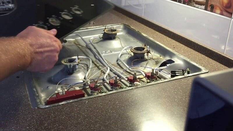
The tip of the temperature sensor is rigidly fixed near the burner or burner by means of a nut. It is possible that it boiled during operation and does not immediately unscrew.
In this case, it is not recommended to press hard on the wrench, as it is possible to break the fastener and damage the plate. You will first need to treat the connection with a special aerosol to dissolve scale. Algorithm replacing thermocouple on gas stove:
Using a wrench, unscrew the nuts that secure the temperature sensor to the solenoid valve
Carefully take out one of the working zones of the temperature sensor. Check out the work area
If it is covered with various contaminants or the surface is damaged by oxidation processes, it will need to be cleaned with fine sandpaper. The second tip of the sensor to the e-valve is mounted by means of a threaded connection or 2 crimp connections. It's not hard to remove them. Check the sensor with a multimeter.One of the tips is attached to a multimeter, and the second is heated with a conventional lighter. The device should show a value of at least 20 mV. A good primary sensor is installed in reverse order. With one tip, it is strengthened near the burner, and with the other to the electromagnet.
The user of the gas stove, who independently decided to replace the faulty thermocouple, needs to pay attention to its design when choosing. It is better to use a native thermocouple according to the modification of the gas stove
All thermocouples are produced in different lengths from 45 to 120 cm, which is associated with the design of the plates
When installing, it is important to pay attention to the fact that the sensor conductors in the area up to the valve must not be overtightened or dangling. Their connection with the valve must be rigid, a free connector in this connection is not allowed.

Next, find a thermocouple and disconnect it from the flame divider in the oven. The performance test is carried out similarly to the above algorithm.


Before removing the thermocouple from the gas column, you will need two open-end wrenches 14 or 15, depending on the specific modification of the column. On many of them, the temperature sensor is fixed with screws. Further actions are similar as for a gas stove.
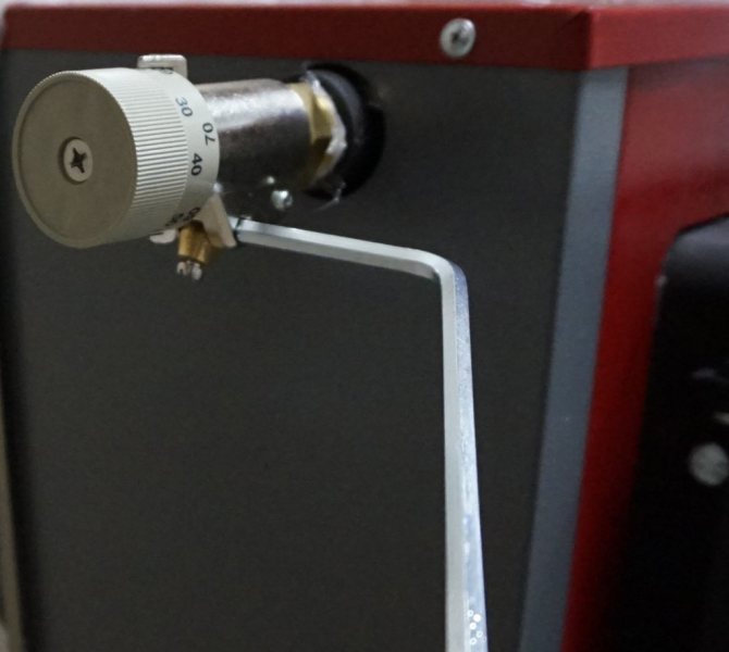
Design and principle of operation
The scheme of the device is quite simple. The main structural elements are:
- temperature control knob;
- stem and guide;
- actuating mechanism;
- immersion sleeve;
- temperature sensitive element;
- spring;
- drive lever;
- fixing screws of the handle and lever;
- chain.
The main component is a sensor that responds to temperature fluctuations.It interacts with a spring, which, when heated or cooled, activates the working part (sleeve and rod).
That, in turn, is connected by means of a mechanical drive to the fuel compartment damper. The draft regulator for solid fuel boilers, under certain conditions, opens and closes the door, maintaining the set temperature.
The principle of operation of the device is banal, but still effective. When the damper is slightly opened, more air enters the firebox. Due to this, the combustion of fuel occurs more intensively, more heat is released, the room warms up more efficiently. When the damper closes, the fuel is supplied with less oxygen and hardly smolders.
If we briefly describe the operation of the draft regulator, based on design features, we get the following scheme:
- when the heat load decreases, the thermostatic sensor reacts to fluctuations;
- the sensor increases the tension of the spring;
- the spring raises the lever;
- damper opens;
- combustion intensifies.
To reduce the intensity of the process, the steps are performed in reverse order.
On the body of the regulator there is a handle with a temperature scale. This sets the required minimum value. The temperature will rise as needed, but will never fall below the set level.
Health check
If problems are observed in the operation of the boiler, then the sensor may need to be replaced. For example, if the burner is switched off regularly, but there are no problems in the combustion gas exhaust system. You also need to check the operation of the device when it periodically turns off after 20-30 minutes.
To check the health of the boiler sensor, you need to consider 3 ways:
- Attach a regular mirror near the device.If the sensor is working properly, then the surface of the mirror should not be covered with condensate.
- An easy way to check by partially closing the chimney. A working sensor will promptly give a signal, and the equipment will turn off.
- If a double-circuit boiler is used as heating equipment, then to check the device, you can switch it to the DHW mode, without heat supply. Then open the tap on a powerful jet of water. Here the situation is reversed - turning off the sensor will be a sign of its problematic operation.
There are many manufacturers of thrust sensors. Among them are such market leaders as Junkers, KAPE, Sitgroup, Eurosit. Some boiler manufacturers (Baxi, Danko) produce appliances for their heating equipment
It is necessary to select the sensors correctly for the equipment that is used (gas water heaters, wall-mounted or floor-standing boilers).
It is important to periodically check the health of the boiler draft sensor
The principle of operation of the sensor
The gas boiler works by burning blue fuel. Naturally, in this case, combustion products are released. If they get into the room, then this is fraught with severe poisoning of all residents of the house, up to and including death. Therefore, the design of the column provides for connection to the chimney, through which all harmful substances are removed to the street.


Naturally, for high-quality removal, the ventilation shaft must have impeccable draft. But it happens that some kind of violation occurs - for example, the chimney can become clogged with debris or soot. If in such a situation the boiler stubbornly continues to burn fuel, then the combustion products will inevitably go into the house.
To prevent this, an element such as a chimney draft sensor is included in the design of the gas boiler. It is located in the place that is located between the ventilation duct and the equipment case. The type of sensor depends on the type of boiler:
- in a boiler with an open combustion chamber, the protective sensor is a metal plate to which a contact is connected. This plate is the indicator that monitors the temperature increase. The fact is that normally escaping gases are usually heated to 120-140 degrees. If the outflow is disturbed, and they begin to accumulate, then this value increases. The metal from which the plate is made reacts to such a situation and expands. The contact attached to the element is displaced and closes the valve responsible for the gas supply. Thus, the combustion process stops, and at the same time, the entry of a new portion of harmful substances is prevented;
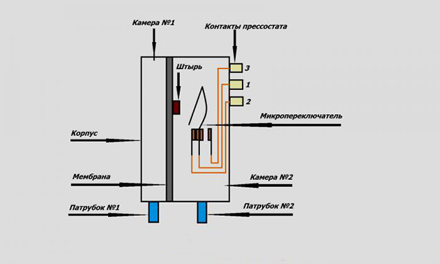
- in a boiler with a closed combustion chamber, the products are removed through a coaxial channel, while a fan is used. The sensor in this case is a pneumatic relay with a membrane. It reacts not to temperature, but to the flow rate. While it is within the acceptable range, the membrane is bent, and the contacts are in the closed position. When the flow rate becomes weaker than necessary, the membrane straightens, the contacts open, and this leads to the blocking of the gas supply valve.
As you can see, if the draft sensor is triggered, turning off the gas column, this means some kind of malfunction in the equipment. For example, it could be:
- initially poor quality traction. This is the first and main reason why the sensor can work.As a rule, this phenomenon is associated with improper installation of the exhaust structure. If the products of combustion are poorly drawn out, then this is a danger to all living things in the house;
- reverse thrust. This phenomenon occurs when an air lock forms in the chimney. Gases, which normally should move to the very top of the pipe and then go outside, cannot overcome this obstacle and return back, filling the room with themselves. The effect of reverse draft can occur if the thermal insulation of the chimney is made very poorly. The temperature difference leads to the formation of air congestion;
- chimney blockage. It may seem to inexperienced owners that the pipe leading to the roof simply cannot be clogged with anything. In fact, there are many factors that lead to clogging. The first one is birds. They can make nests on the pipe, which then fall down. Yes, and the birds themselves often manage to get stuck in the chimney, and then die there. In addition to birds, one should also take into account the possibility of getting, for example, leaves, as well as the deposition of soot on the inner walls of the pipe. If the chimney is clogged, the draft intensity becomes too low, and there is only one way out - cleaning;
- strong wind. If the pipe is not properly positioned, gusts can enter it and blow out the burner. Naturally, in such cases, the sensor shuts off the fuel supply. To avoid such a danger, it is necessary to purchase and install a stabilizer.
Diagnosis of problems and ways to solve them
If your geyser, equipped with an automatic security system, does not work, you need to make sure that the problem lies in the operation of one of the sensors:
- If your draft sensor works, then in the room, most likely, at this moment you will feel the smell of burning or gas. To make sure that it is really the wrong draft, bring your palm or a piece of paper to the chimney. If the draft is broken and the air goes from the chimney into the room, then the solution to the problem often lies in calling a stove-maker who will clean the chimney from soot and combustion products that have settled in it.
- The overheat sensor will work in your geyser if the cause of the excessive temperature rise is the contamination of the heat exchanger. You need to act as follows: open windows and doors, wait until the room is cleaned with fresh air and the boiler cools down, then contact a qualified specialist.
- If you have an ionization sensor installed, it may cause the igniter to fail to ignite due to the igniter nozzles being clogged with soot, and the safe ignition time programmed in the flame detector will expire. The way out in this situation is to clean the nozzles at the igniter and try again to ignite. If it is not successful, you should contact a qualified master.
Author's note: Hello friends! A geyser is a rather complex structure, consisting of many elements. Each of them plays an important role in the operation of the device. In the event of a breakdown of some of these elements, the problem is immediately visible, this does not require any testing.But how to check the draft sensor for a gas column? And what is this detail for? This is what will be discussed in today's article.
In general, a geyser is an excellent heating device. No wonder it is the most popular among owners of both apartments and private houses. The boiler is highly efficient, does not require too much maintenance, and the fuel used usually costs literally a penny.
The only drawback of this equipment is the possible danger of its operation in case of any malfunction. Everyone knows that a gas leak, for example, can have terrible consequences, up to an explosion, destruction of a house and death of people. Therefore, each element of the column must work perfectly, any malfunction must be corrected immediately, and a categorically failed part must be replaced.
Therefore, it is extremely important to detect damage in a timely manner. To do this, regular checks of the system are carried out, and, as a rule, they are performed by specialists from the gas service. But you yourself can periodically examine some of the elements on which the safety of people living in the house depends.
One of these parts of the design is the thrust sensor.
But you yourself can periodically examine some of the elements on which the safety of people living in the house depends. One of these parts of the design is the thrust sensor.
Briefly about the three-way valve mechanism
The device of a three-way valve for a domestic gas boiler and other gas equipment is quite simple, despite the seemingly complex shape.It should be noted that each manufacturer has a significantly different design of valves, but the principle of operation remains virtually unchanged.
Traditionally, the body of the device is made of bronze. Working elements, for example, a rod, springs, are made of steel. The diaphragm is usually made of rubber. A double ring element is used to seal the stem. Connecting parts (fittings) can be threaded or soldered, depending on the model of the three-way valve.
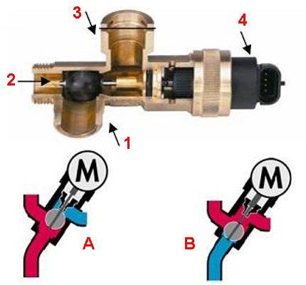
One of the widely used versions of the three-way valve: 1, 2 - angular through passage transport channel; 1, 3 - direct through transport channel; 4 - drive head; A - flow transport in heating mode; B - flow transport in DHW mode
Usually, an electromechanical drive is used in conjunction with the device. Thanks to its work, two-point regulation is carried out.
So, the drive for a three-way valve can be manual, electromechanical (thermostatic, with a thermal head), electric, hydraulic.
The principle of operation of a three-way valve for a gas boiler circuit is approximately as follows: when the device is in the normally open transport mode, the direct through-flow transport channel is accordingly open. The corner passageway remains closed.


A different state of the mechanism ensures the opening of the corner transport channel and the blocking of the direct transport channel, respectively. Intermediate positions of the stem and blade of the three-way valve are also possible.
We spoke in more detail about the device and principle of operation of a three-way valve in the following material.
Conclusions and useful video on the topic
The video discusses the structural details of the thrust sensors, the location of these components and their principle of operation:
If professional craftsmen are quite familiar with gas equipment, for the average user, troubleshooting a gas boiler is a “dark forest”. In addition, the handling of gas systems in the absence of appropriate knowledge is fraught with serious consequences.
Therefore, when there is a desire to independently replace or repair the same thrust sensor or some other equipment of the gas column, you first need to at least study the system. But the best way to eliminate defects in the gas system is to contact specialists.
Would you like to supplement the above material with useful comments on the principle of operation of the thrust sensor? Or would you like to share your sensor test experience with other users? Write your remarks and comments in the block below, add unique photos of your own testing.