- Advantages and disadvantages of electronic ballast
- general information
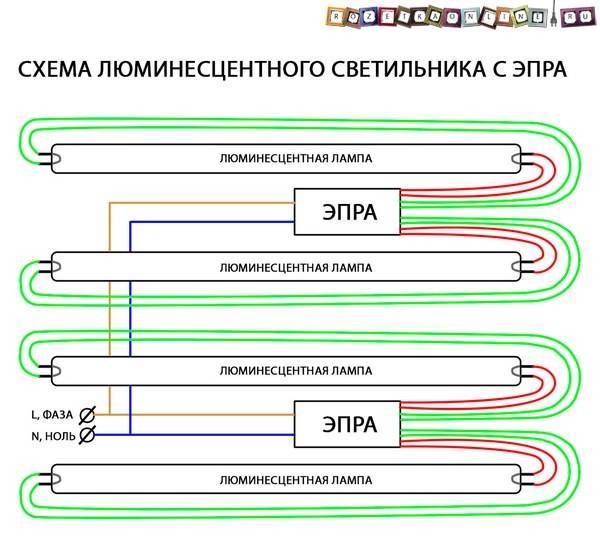
- Wiring diagram with electronic ballast
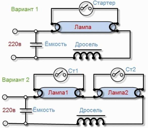
- Schemes with a starter
- Two tubes and two chokes
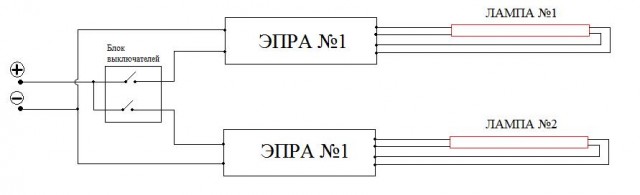
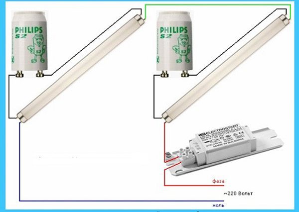
- Wiring diagram for two lamps from one throttle (with two starters)
- Kinds
- electromagnetic
- Electronic
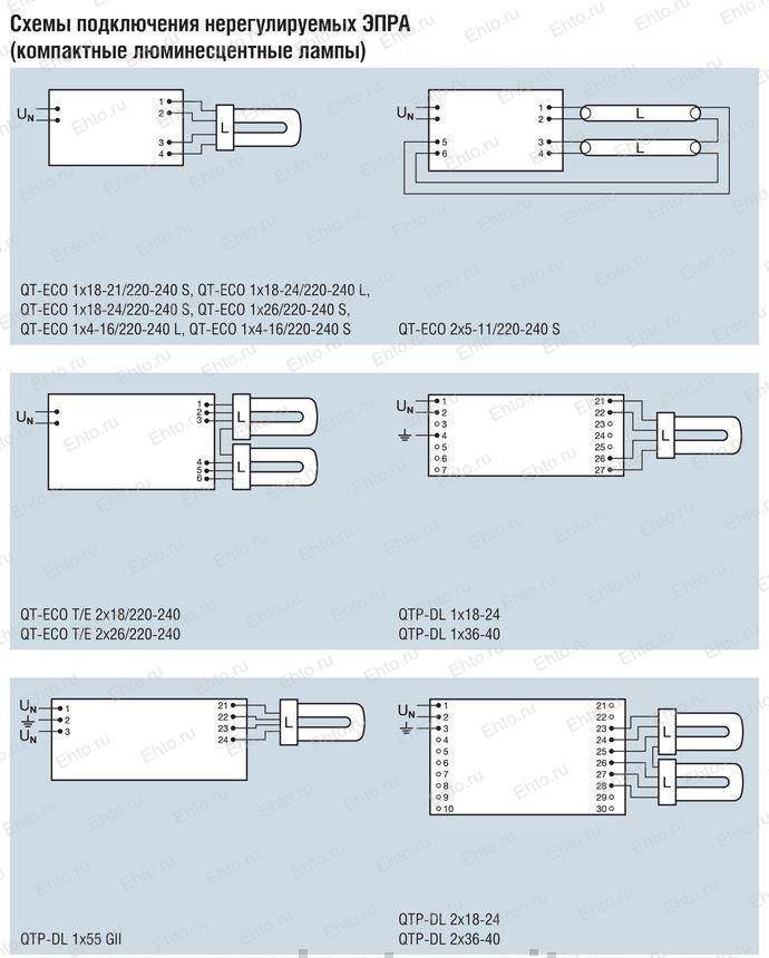
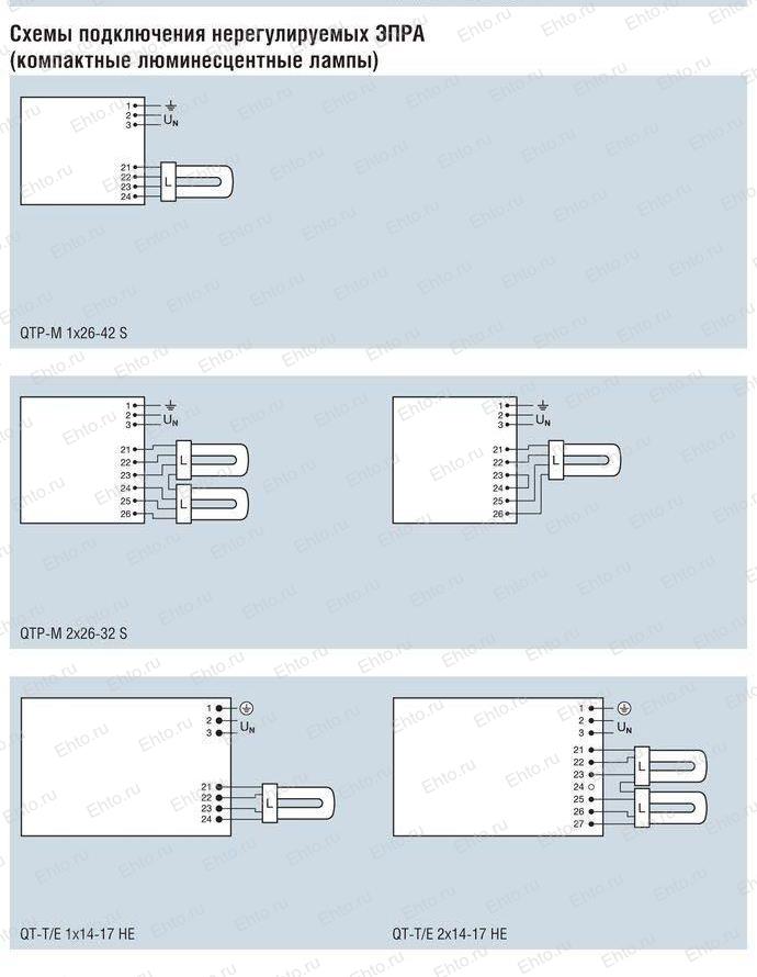
- For compact fluorescent lamps
- Connecting a lamp without a choke
- Connection via modern electronic ballast
- Circuit Features
- The principle of operation of a fluorescent lamp
- What is a choke for?
- Differences between a choke and an electronic ballast
- Connection using electromagnetic ballast or electronic ballast
- Scheme with empra
- Scheme with electronic ballast
- Fluorescent lamp device
- Electronic ballast for fluorescent lamps: what is it
- Wiring diagram, start
- Breakdown detection and repair work
Advantages and disadvantages of electronic ballast
The use of electronic ballasts makes significant positive changes in the operation of fluorescent lighting devices. The main advantages of EPR are the following:
- The maximum light power is noticeably increased while reducing the amount of electricity consumed by the power supply.
- A distinctive feature of old fluorescent lamps - flickering - is completely absent.
- There is almost no noise and buzz during the operation of the lamp.
- Extending the life of fluorescent lamps.
- Convenient settings and control of the brightness of the light flux.
- Lamps with electronic equipment are not at all affected by voltage surges and drops in the supply network.
The main disadvantage of electronic ballasts is their high cost compared to electromagnetic devices. Currently, the latest technologies in this area are constantly being developed and improved. In this regard, the price of electronic products is gradually approaching the cost of old equipment.
general information
The design of the device is extremely simple. It consists of a choke that smoothes out the ripple, a starter as a starter and a capacitor to stabilize the voltage. But this device is already considered obsolete.
The models have been improved and now they are called electronic ballasts (EPR). They belong to the same type of devices as ballasts, but they are based on electronics. In fact, this is a small board with several elements. The compact design makes it easy to install.
All PRAs are conditionally divided into two types:
- consisting of a single block;
- consisting of several parts.
Devices can also be classified according to the type of lamps: devices for halogen, LED and gas discharge. To understand what an EMCG is, and how it differs from an electronic ballast, it is necessary to consider the performance characteristics. They can be electronic and electromagnetic.
Wiring diagram with electronic ballast
Currently, electromagnetic ballast is gradually falling out of use and is being replaced by more modern electronic ballasts - electronic ballasts. Its main difference lies in the high voltage frequency of 25-140 kHz.It is with such indicators that the current is supplied to the lamp, which can significantly reduce flicker and make it safe for the eyes.
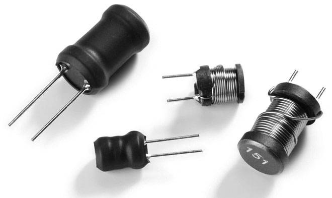
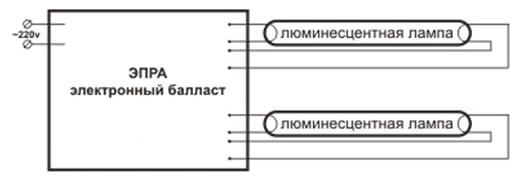
The electronic ballast connection diagram with all explanations is indicated by the manufacturers on the bottom of the case. It also indicates how many lamps and what power can be connected. The appearance of the electronic ballast is a compact unit with terminals brought out. Inside is a printed circuit board on which structural elements are assembled.
Due to its small size, the unit can even be placed inside compact fluorescent lamps. In this case, in fact, a connection scheme for fluorescent lamps without a starter is used, since it is not required in electronic devices. The switching process is much faster compared to electromagnetic equipment.
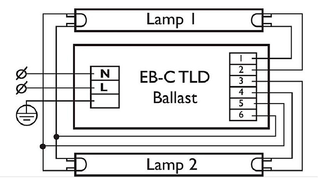
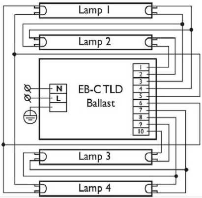
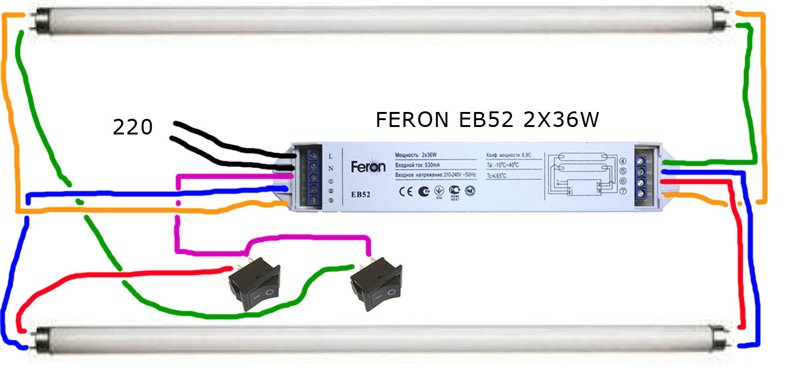
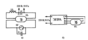
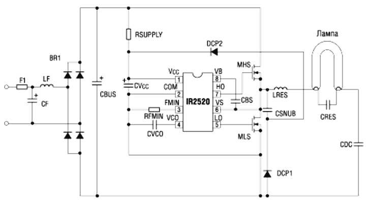
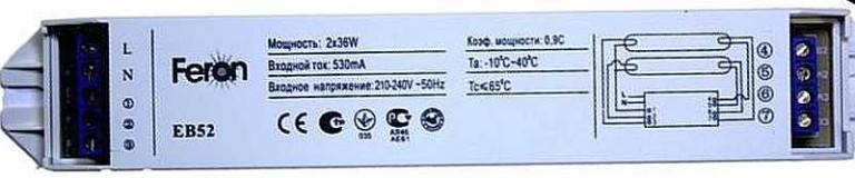
A typical connection diagram is shown in the figure. The first pair of lamp contacts is connected to contacts No. 1 and 2, and the second pair is connected to contacts No. 3 and 4. Supply voltage is applied to contacts L and N located at the input.
The use of electronic ballasts allows you to increase the life of the lamp, including with two lamps. Electricity consumption is reduced by about 20-30%. Flickering and buzzing are not felt at all by a person. The presence of a scheme specified by the manufacturer facilitates and simplifies the installation and replacement of products.
Schemes with a starter
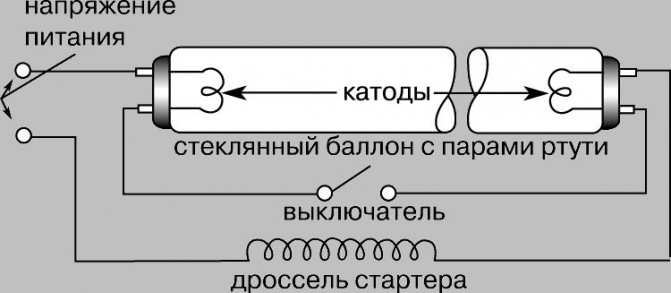
The very first circuits with starters and chokes appeared. These were (in some versions, there are) two separate devices, each of which had its own socket.There are also two capacitors in the circuit: one is connected in parallel (to stabilize the voltage), the second is located in the starter housing (increases the duration of the starting pulse). All this "economy" is called - electromagnetic ballast. The diagram of a fluorescent lamp with a starter and a choke is in the photo below.
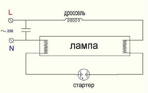
Wiring diagram for fluorescent lamps with a starter
Here's how it works:
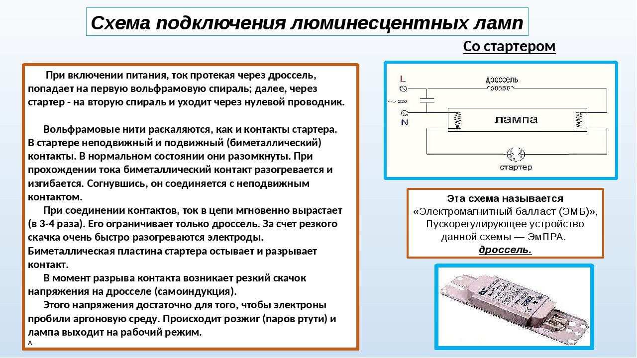
- When the power is turned on, the current flows through the inductor, enters the first tungsten filament. Further, through the starter it enters the second spiral and leaves through the neutral conductor. At the same time, the tungsten filaments gradually heat up, as do the starter contacts.
- The starter has two contacts. One fixed, the second movable bimetallic. In the normal state, they are open. When current is passed, the bimetallic contact heats up, which causes it to bend. Bending, it connects to a fixed contact.
- As soon as the contacts are connected, the current in the circuit instantly increases (2-3 times). It is limited only by the throttle.
- Due to the sharp jump, the electrodes heat up very quickly.
- The bimetallic starter plate cools down and breaks contact.
- At the moment of breaking the contact, a sharp voltage jump occurs on the throttle (self-induction). This voltage is sufficient for the electrons to break through the argon medium. Ignition occurs and gradually the lamp enters the operating mode. It comes after all the mercury has evaporated.
The operating voltage in the lamp is lower than the mains voltage for which the starter is designed. Therefore, after ignition, it does not work. In a working lamp, its contacts are open and it does not participate in its work in any way.
This circuit is also called electromagnetic ballast (EMB), and the operation circuit of an electromagnetic ballast is EmPRA. This device is often referred to simply as a choke.
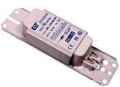
One of the EMPRA
The disadvantages of this fluorescent lamp connection scheme are enough:
- pulsating light, which negatively affects the eyes and they quickly get tired;
- noise during start-up and operation;
- inability to start at low temperatures;
- long start - from the moment of switching on, about 1-3 seconds pass.
Two tubes and two chokes
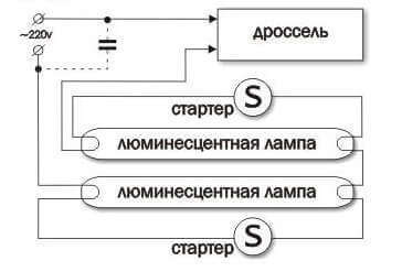
In luminaires for two fluorescent lamps, two sets are connected in series:
- the phase wire is fed to the inductor input;
- from the throttle output it goes to one contact of the lamp 1, from the second contact it goes to the starter 1;
- from starter 1 goes to the second pair of contacts of the same lamp 1, and the free contact is connected to the neutral power wire (N);
The second tube is also connected: first the throttle, from it - to one contact of the lamp 2, the second contact of the same group goes to the second starter, the starter output is connected to the second pair of contacts of the lighting device 2 and the free contact is connected to the neutral input wire.
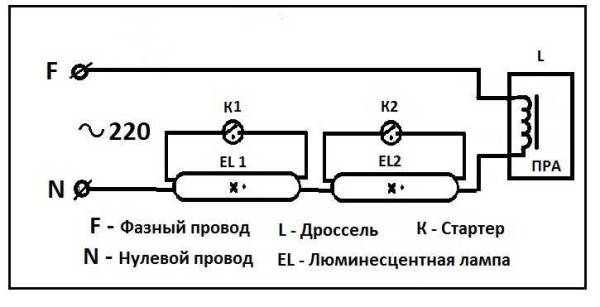
Connection diagram for two fluorescent lamps
The same connection diagram for a two-lamp fluorescent lamp is shown in the video. It might be easier to deal with the wires this way.


Wiring diagram for two lamps from one throttle (with two starters)
Almost the most expensive in this scheme are chokes. You can save money and make a two-lamp lamp with one throttle. How - see the video.
Kinds
Today, such types of ballast devices are widely represented on the market, such as:
- electromagnetic;
- electronic;
- ballasts for compact lamps.
These categories are marked by reliable performance and provide long life and ease of use for all fluorescent lamps. All these devices have an identical principle of operation, but differ in some points.
electromagnetic
These ballasts are applicable for lamps connected to the mains with a starter. The initially arising discharge intensively heats up and closes the bimetallic electrode elements. There is a sharp increase in the operating current.
Electromagnetic ballast is easy to recognize by its appearance. The design is more massive compared to the electronic prototype.
When the starter fails, a false start occurs in the electromagnetic ballast circuit. When power is supplied, the lamp starts flashing, followed by a steady supply of electricity. This feature significantly reduces the working life of the light source.
| pros | Minuses |
|---|---|
| The high level of reliability proved by practice and time. | Long start - at the first stage of operation, the start is carried out in 2-3 seconds and up to 8 seconds by the end of the service life. |
| Simplicity of design. | Increased power consumption. |
| Ease of use of the module. | Lamp flickering at 50 Hz (strobe effect). It negatively affects a person who is in a room with this type of lighting for a long time. |
| Affordable price for consumers. | Throttle hum is heard. |
| The number of manufacturing firms. | Significant design weight and bulkiness. |
Electronic
Today, magnetic and electronic ballasts are used, which in the first case consist of a microcircuit, transistors, dinistors and diodes, and in the second - of metal plates and copper wire. By means of a starter, the lamps are started, and as a single function of this element with a ballast in one circuit, a phenomenon is organized in the electronic version of the part.
- light weight and compactness;
- smooth fast start;
- unlike electromagnetic designs, which require a 50 Hz network for operation, high-frequency magnetic counterparts operate without noise from vibration and flicker;
- reduced heating losses;
- power factors in electronic circuits reach 0.95;
- extended service life and safety of use are provided by several types of protection.
| Advantages | Flaws |
|---|---|
| Automatic adjustment of the ballast for different types of lamps. | Higher cost compared to electromagnetic models. |
| Instant inclusion of the lighting device, without additional load on the device. | |
| Saving electricity consumption up to 30%. | |
| The heating of the electronic module is excluded. | |
| Smooth light supply and no noise effects during lighting. | |
| Extending the life of fluorescent lamps. | |
| Additional protection guarantees an increase in the degree of fire safety. | |
| Reduced risks during operation. | |
| Smooth supply of light flux eliminates fatigue. | |
| Absence of negative functions in conditions of low temperatures. | |
| Compact and lightweight design. |
For compact fluorescent lamps
Compact types of fluorescent lamps are represented by devices similar to the incandescent lamp types E27, E40 and E14.In such schemes, electronic ballasts are built into the cartridge. In this design, repair in the event of a breakdown is excluded. It will be cheaper and more practical to purchase a new lamp.
Connecting a lamp without a choke
Changes can be made to the standard wiring diagram if necessary. One of these options is the connection of a fluorescent light bulb without a choke, which reduces the risk of burning out the light source. In the same way, it is possible to assemble and connect fluorescent lamps that have failed.
In the circuit shown in the figure, there is no incandescent filament, and power is supplied through a diode bridge that creates a voltage with a constant increased value. This connection method leads to the fact that the bulb of the lighting device may eventually darken on one side.
In practice, such a circuit for switching on a fluorescent lamp is quite easy to implement, using old parts and components for this purpose. You will need the lamp itself, with a power of 18 watts, a diode bridge in the form of a GBU 408 assembly, capacitors with a capacity of 2 and 3 nF and an operating voltage of not more than 1000 volts. If the power of the lighting device is higher, then capacitors with increased capacitance, assembled according to the same principle, will be required. Diodes for the bridge should be selected with a voltage margin. The brightness of the glow with this assembly will be slightly lower than with the standard version with a throttle and a starter.
In addition, when solving the problem of how to connect a fluorescent lamp, it is possible to avoid most of the shortcomings that are typical for conventional lamps of this type using EM ballasts.
The lamp with a diode bridge is connected easily, it will light up almost instantly, there will be no noise during operation. An important condition is the absence of a starter, which often burns out as a result of long-term operation. The use of burnt out lamps makes it possible to save. In the role of a choke, standard models of incandescent bulbs are used; bulky and expensive ballast is not required.
Connection via modern electronic ballast
Connecting a light source with electronic ballast
Circuit Features
Modern connectivity. An electronic ballast is included in the circuit - this economical and improved device provides a much longer service life of fluorescent lamps compared to the above option.
In circuits with electronic ballast, fluorescent lamps operate at increased voltage (up to 133 kHz). Thanks to this, the light is even, without flickering.
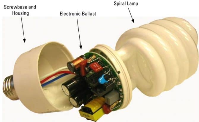
Modern microcircuits make it possible to assemble specialized starting devices with low power consumption and compact dimensions. This makes it possible to place the ballast directly into the lamp base, which makes it possible to manufacture small-sized lighting fixtures screwed into an ordinary socket, standard for incandescent lamps.
At the same time, microcircuits not only provide power to the lamps, but also smoothly heat up the electrodes, increasing their efficiency and increasing their service life. It is these fluorescent lamps that can be used in combination with dimmers - devices designed to smoothly control the brightness of light bulbs. You cannot connect a dimmer to fluorescent lamps with electromagnetic ballasts.
By design, the electronic ballast is a voltage converter. A miniature inverter transforms direct current into high-frequency and alternating current. It is he who enters the electrode heaters. With increasing frequency, the heating intensity of the electrodes decreases.
Turning on the converter is organized in such a way that at first the current frequency is at a high level. The fluorescent lamp, in this case, is included in the circuit, the resonant frequency of which is much less than the initial frequency of the converter.


Further, the frequency begins to gradually decrease, and the voltage on the lamp and the oscillatory circuit increase, due to which the circuit approaches resonance. The intensity of electrode heating also increases. At some point, conditions are created that are sufficient to create a gas discharge, as a result of which the lamp begins to give light. The lighting device closes the circuit, the mode of operation of which changes in this case.
When using electronic ballasts, the lamp connection diagrams are designed in such a way that the control device has the opportunity to adapt to the characteristics of the light bulb. For example, after a certain period of use, fluorescent lamps require a higher voltage to create an initial discharge. The ballast will be able to adapt to such changes and provide the necessary quality of lighting.
Thus, among the numerous advantages of modern electronic ballasts, the following points should be highlighted:
- high operating efficiency;
- gentle heating of the electrodes of the lighting device;
- smooth turning on of the light bulb;
- no flicker;
- possibility of use in conditions of low temperatures;
- independent adaptation to the characteristics of the lamp;
- high reliability;
- light weight and compact size;
- increase the life of lighting fixtures.
There are only 2 disadvantages:
- complicated connection scheme;
- higher requirements for the correct installation and the quality of the components used.
EXEL-V stainless steel explosion-proof fluorescent luminaires
The principle of operation of a fluorescent lamp
A feature of the operation of fluorescent lamps is that they cannot be directly connected to the power supply. The resistance between the electrodes in the cold state is large, and the amount of current flowing between them is insufficient for a discharge to occur. Ignition requires a high voltage pulse.
A lamp with an ignited discharge is characterized by low resistance, which has a reactive characteristic. To compensate for the reactive component and limit the flowing current, a choke (ballast) is connected in series with the luminescent light source.
Many do not understand why a starter is needed in fluorescent lamps. The inductor, included in the power circuit together with the starter, generates a high voltage pulse to start a discharge between the electrodes. This happens because when the starter contacts are opened, a self-induction EMF pulse of up to 1 kV is formed at the inductor terminals.
 Watch this video on YouTube
What is a choke for?
The use of a choke for fluorescent lamps (ballast) in power circuits is necessary for two reasons:
- starting voltage generation;
- limiting the current through the electrodes.
The principle of operation of the inductor is based on the reactance of the inductor, which is the inductor. Inductive reactance introduces a phase shift between voltage and current equal to 90º.
Since the current-limiting quantity is inductive reactance, it follows that chokes designed for lamps of the same power cannot be used to connect more or less powerful devices.
Tolerances are possible within certain limits. So, earlier, the domestic industry produced fluorescent lamps with a power of 40 watts. A 36W inductor for modern fluorescent lamps can be safely used in power circuits of outdated lamps and vice versa.
Differences between a choke and an electronic ballast
The throttle circuit for switching on luminescent light sources is simple and highly reliable. The exception is the regular replacement of starters, since they include a group of NC contacts for generating start pulses.
At the same time, the circuit has significant drawbacks that forced us to look for new solutions for turning on lamps:
- long start-up time, which increases as the lamp wears out or the supply voltage decreases;
- large distortion of the mains voltage waveform (cosf<0.5);
- flickering glow with double the frequency of the power supply due to the low inertia of the luminosity of the gas discharge;
- large weight and size characteristics;
- low-frequency hum due to vibration of the plates of the magnetic throttle system;
- low reliability of starting at low temperatures.
Checking the choke of fluorescent lamps is hampered by the fact that devices for determining short-circuited turns are not very common, and using standard devices, one can only state the presence or absence of a break.
To eliminate these shortcomings, circuits of electronic ballasts (electronic ballasts) have been developed. The operation of electronic circuits is based on a different principle of generating a high voltage to start and maintain combustion.
 Watch this video on YouTube
The high voltage pulse is generated by the electronic components and a high frequency voltage (25-100 kHz) is used to support the discharge. The operation of the electronic ballast can be carried out in two modes:
- with preliminary heating of electrodes;
- with cold start.
In the first mode, low voltage is applied to the electrodes for 0.5-1 second for initial heating. After the time has elapsed, a high-voltage pulse is applied, due to which the discharge between the electrodes is ignited. This mode is technically more difficult to implement, but increases the service life of the lamps.
The cold start mode is different in that the start voltage is applied to the cold electrodes, causing a quick start. This starting method is not recommended for frequent use, as it greatly reduces the life, but it can be used even with lamps with faulty electrodes (with burnt filaments).
Circuits with an electronic choke have the following advantages:
complete absence of flicker;
wide temperature range of use;
small distortion of the mains voltage waveform;
absence of acoustic noise;
increase the service life of lighting sources;
small dimensions and weight, the possibility of miniature execution;
the possibility of dimming - changing the brightness by controlling the duty cycle of the electrode power pulses.
Connection using electromagnetic ballast or electronic ballast
Structural features do not allow connecting LDS directly to a 220 V network - operation from such a voltage level is impossible. To start, a voltage of at least 600V is required.


With the help of electronic circuits, it is necessary to sequentially provide the necessary modes of operation, each of which requires a certain level of voltage.
Operating modes:
- ignition;
- glow.
The launch consists in applying high voltage pulses (up to 1 kV) to the electrodes, as a result of which a discharge occurs between them.
Certain types of ballasts, before starting, heat the spiral of electrodes. Incandescence helps to start the discharge easier, while the filament overheats less and lasts longer.
After the lamp lights up, the power is supplied by alternating voltage, the energy-saving mode is turned on.
In devices manufactured by industry, two types of ballasts (ballasts) are used:
- electromagnetic ballast EMPRA;
- electronic ballast - electronic ballast.
The schemes provide for a different connection, it is presented below.
Scheme with empra
The composition of the electrical circuit of the lamp with electromagnetic ballasts (Empra) includes the following elements:
- throttle;
- starter;
- compensating capacitor;
- Fluorescent Lamp.
At the moment of power supply through the circuit: choke - LDS electrodes, voltage appears on the starter contacts.
The bimetallic contacts of the starter, which are in the gaseous medium, when heated, close.Because of this, a closed circuit is created in the lamp circuit: contact 220 V - choke - starter electrodes - lamp electrodes - contact 220 V.
The electrode filaments, when heated, emit electrons, which create a glow discharge. Part of the current begins to flow through the circuit: 220V - choke - 1st electrode - 2nd electrode - 220 V. The current in the starter drops, the bimetallic contacts open. According to the laws of physics, at this moment, an EMF of self-induction occurs on the contacts of the inductor, which leads to the appearance of a high-voltage pulse on the electrodes. There is a breakdown of the gaseous medium, an electric arc occurs between opposite electrodes. LDS begins to glow with a steady light.
Further, a choke connected in line provides a low level of current flowing through the electrodes.
A choke connected to an alternating current circuit works as an inductive reactance, reducing the efficiency of the lamp by up to 30%.
Attention! In order to reduce energy losses, a compensating capacitor is included in the circuit, without it the lamp will work, but power consumption will increase
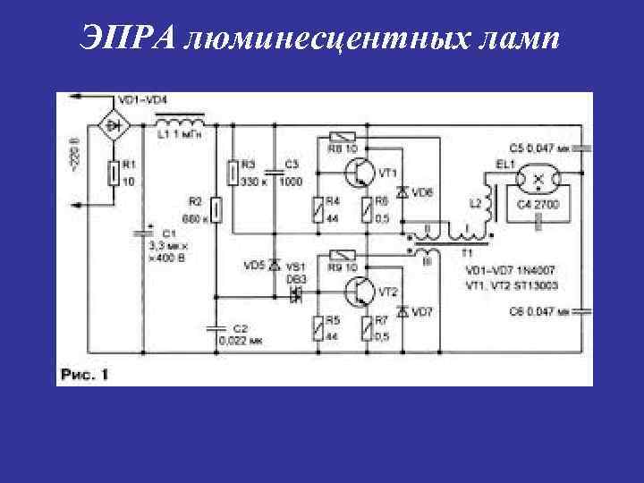
Scheme with electronic ballast
Attention! In retail, electronic ballasts are often found under the name electronic ballast. Sellers use the driver name to refer to power supplies for LED strips
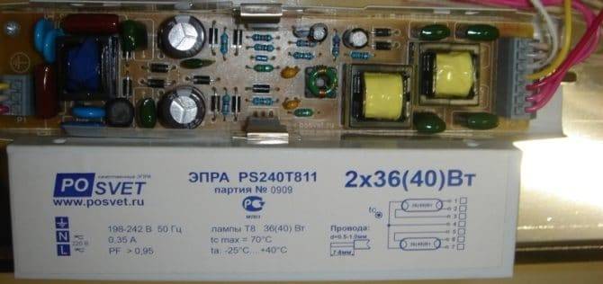
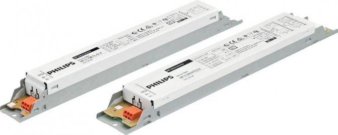
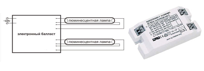
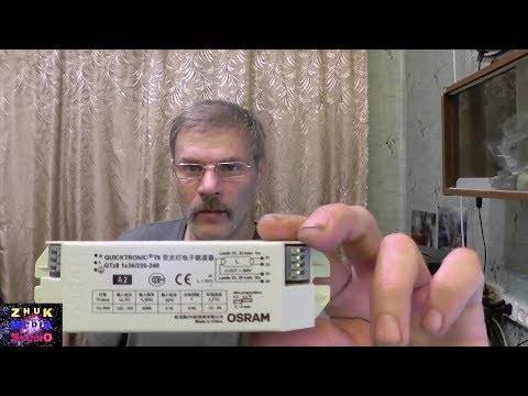
Appearance and design of an electronic ballast designed to turn on two lamps, each with a power of 36 watts.
In circuits with electronic ballasts, the physical processes remain the same. Some models provide preheating of the electrodes, which increases the life of the lamp.


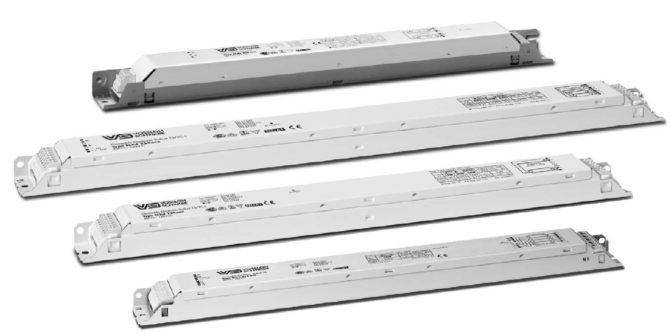
The figure shows the appearance of electronic ballasts for devices of various power.
Dimensions allow you to place electronic ballasts even in the E27 base.
Compact ESL - one of the types of fluorescent ones can have a g23 base.
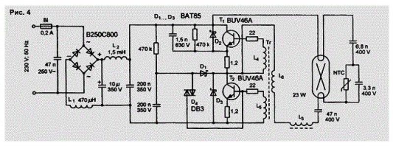
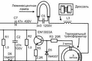
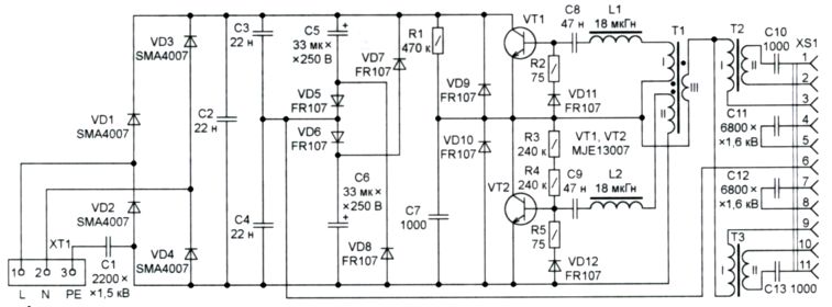
The figure shows a simplified functional diagram of the electronic ballast.
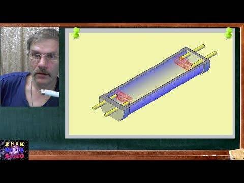
Fluorescent lamp device
The fluorescent lamp belongs to the category of classical low-pressure discharge light sources. The glass bulb of such a lamp always has a cylindrical shape, and the outer diameter can be 1.2 cm, 1.6 cm, 2.6 cm or 3.8 cm.
The cylindrical body is most often straight or U-curved. Legs with electrodes made of tungsten are hermetically soldered to the end ends of the glass bulb.
Light bulb device
The outer side of the electrodes is soldered to the base pins. From the flask, the entire air mass is carefully pumped out through a special stem located in one of the legs with electrodes, after which the free space is filled with an inert gas with mercury vapor.
On some types of electrodes, it is mandatory to apply special activating substances, represented by barium oxides, strontium and calcium, as well as a small amount of thorium.
Electronic ballast for fluorescent lamps: what is it
A fluorescent lamp, which is equipped with an electronic ballast, starts working after going through several necessary phases.
Namely:
- Inclusion. From the rectifier, the current enters the capacitor, where the ripple frequency is smoothed out. After that, a high DC voltage begins to drop to the half-bridge inverter, and at this time, the low voltage capacitor of the lamp electrode and the microcircuit begin to charge.
- preheating. After generating oscillations, the current begins to flow through the center of the half-bridge and the lamp electrode.Gradually, the oscillation frequencies will decrease, and the voltage will increase. This whole process, on average, takes about 1.5 seconds after switching on. In this case, the lamp will not turn on before the set time, so the voltage is low. During this time, the lamp has time to heat up.
- Ignition. The half-bridge frequency is reduced to a minimum. Fluorescent lamps have a minimum ignition voltage of 600 volts. The inductor helps the current overcome this value - it increases the voltage, and the lamp turns on.
- Combustion. The current frequency stops at the rated operating frequency. Capacitors are constantly charged during operation. The power of the lamp is in a stable voltage, even if there are voltage fluctuations in the network.
Electronic ballasts are necessary for fluorescent lamps, since thanks to this device there is no strong heating. Therefore, there will be no problems with fire safety. And the device provides a uniform glow. Therefore, lamps with electronic ballasts are in demand.
First you need to prepare the necessary tools and materials: screwdrivers, side cutters, a device that determines the phase of the current, electrical tape, a sharp knife, fasteners. Before installation, you need to find a place where the electronic ballast will be located inside the lamp
It is important to consider the length of all wires and access to the necessary parts. The electronic ballast is attached to the lamp with fasteners
After that, the device is connected to the lamp connector. It must be remembered that the power of the electronic ballast must be greater than that of the lamp itself.
Then you should connect all the contacts to the equipment and test. When installed correctly, the lamp will light up without additional heating and flickering.
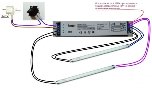
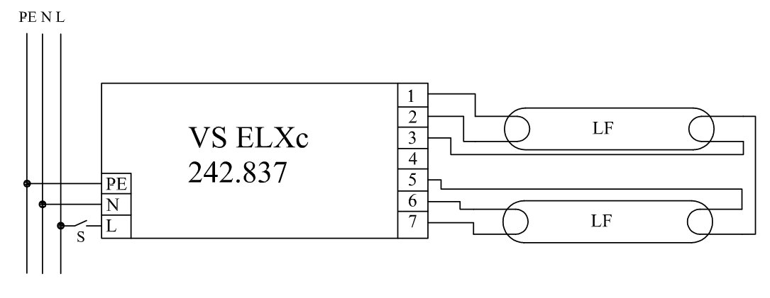
Wiring diagram, start
The ballast is connected on one side to the power source, on the other - to the lighting element. It is necessary to provide for the possibility of installing and fixing electronic ballasts. The connection is made in accordance with the polarity of the wires. If you plan to install two lamps through the gear, use the option of parallel connection.
The schema will look like this:
 A group of gas-discharge fluorescent lamps cannot work normally without a ballast. Its electronic version of the design provides a soft, but at the same time almost instantaneous start of the light source, which further prolongs its service life.


The lamp is ignited and maintained in three stages: heating of the electrodes, the appearance of radiation as a result of a high-voltage pulse, and maintaining combustion is carried out by means of a constant supply of a small voltage.
Breakdown detection and repair work
If there are problems in the operation of gas-discharge lamps (flickering, no glow), you can make repairs yourself. But first you need to understand what the problem is: in the ballast or in the lighting element. To check the operability of electronic ballasts, a linear light bulb is removed from the fixtures, the electrodes are closed, and a conventional incandescent lamp is connected. If it lights up, the problem is not with the ballast.
Otherwise, you need to look for the cause of the breakdown inside the ballast. To determine the malfunction of fluorescent lamps, it is necessary to “ring out” all the elements in turn. You should start with a fuse. If one of the nodes of the circuit is out of order, it is necessary to replace it with an analogue. The parameters can be seen on the burnt element.Ballast repair for gas discharge lamps requires the use of soldering iron skills.
If everything is in order with the fuse, then you should check the capacitor and diodes that are installed in close proximity to it for serviceability. The voltage of the capacitor must not be below a certain threshold (this value varies for different elements). If all the elements of the control gear are in working order, without visible damage, and the ringing also did not give anything, it remains to check the inductor winding.
Repair of compact fluorescent lamps is carried out according to a similar principle: first, the body is disassembled; the filaments are checked, the cause of the breakdown on the control gear board is determined. Often there are situations when the ballast is fully functional, and the filaments are burned out. Repairing the lamp in this case is difficult to produce. If the house has another broken light source of a similar model, but with an intact filament body, you can combine two products into one.
Thus, electronic ballasts represent a group of advanced devices that ensure the efficient operation of fluorescent lamps. If the light source flickers or does not turn on at all, checking the ballast and its subsequent repair will extend the life of the bulb.


