- Purpose, scope
- Types of smart aggregates
- Devices with dimming function
- Devices with remote control
- Limit switches in large industrial machines
- The main purpose of the switch
- The principle of operation and features of toggle switches
- Limit switch KV-04
- Kinds
- Advantages and disadvantages
- pros
- Minuses
- Who manufactures limit switches
- Device and principle of operation
- Voltage
- Mechanical type limit switches
- Features of automotive limit switches
- Deciding on a denomination
- Example
- Power calculation
- Varieties
- By the nature of the action
- By type of construction
- Varieties
- Scheme of connecting the limit switch to the starter
- Lighting with cross switch in TN-S network
- Machine marking
- Deciphering the designations of circuit breakers
Purpose, scope
Semiconductor devices (Hall sensors) are increasingly being used in switching electronics. However, the reed switches of some devices can compete with them, despite the lag in technical parameters:
- the connections hidden by a surface of a flask guarantee safe work in explosive rooms;
- in devices operating under water, in places with a humid climate;
- in signaling systems based on position control;
- determining the position of the elevator at the current moment;
- keyboard of industrial devices for reliable and long-term operation;
- some samples of television and radio equipment, medical devices and other areas of technology.
Types of smart aggregates
Manufacturers offer a fairly wide range of smart solutions that can work on Wi-Fi, Bluetooth, ZigBee, Z-Wave.
Devices also differ in design features. Some of them are specially designed for connection to a network in which there is a neutral wire. At the same time, for the installation of many products, including most smart dimmers, phase "0" is not required.
Devices with dimming function
A significant part of the models of smart devices for turning on / off the light also successfully play the role of a dimmer - a device that regulates the brightness of lighting fixtures. In this case, all options are saved: a smart device controlled from a smartphone is able to work in automatic mode.
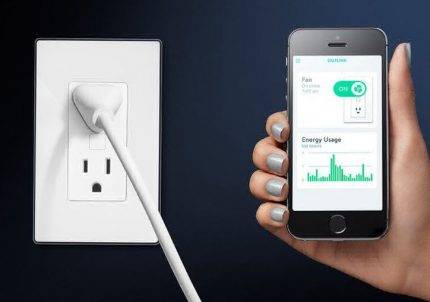
The control module, that is, a device without a key, can be installed in a socket and used like a regular socket. In this case, the device acquires all the above options of a smart device - remote control, programming, automatic operation
Additional features provided by dimmers allow you to significantly expand the area of use of switches.
With their help, it is easy to create a cozy atmosphere in the room, turning on bright lights only if necessary. In addition, dimmers are also widely used by interior designers as lighting control devices.
Devices with remote control
Another type of smart device is a remote switch.In its appearance, it resembles a traditional one, but in fact it is a remote control.
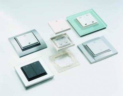
A number of domestic and foreign manufacturers produce key models of smart devices that are installed in sockets instead of traditional switches.
An intelligent device, like a conventional switch, consists of a frame and a button. Since it does not require electrical wiring, it can be installed almost anywhere in the room.
The function of the remote switch is to transmit commands via radio waves to other devices. It necessarily works in conjunction with other devices, for example, together with a dimming switch, which, after receiving a signal, will reduce the light intensity in a burning chandelier.
The same device can also be used to control the operation of a smart outlet.
Limit switches in large industrial machines
People and equipment located in industrial environments are kept safe by the operation of limit switches. These devices usually turn off the machine when the action exceeds its travel or position limit.
In other words, if the robot is malfunctioning, the limit switch will cut off power to the motion control circuit in the same way that a washing machine stops moving when you open the lid.
When you hear the "beep" of a large truck moving backwards, the limit switch was turned on when the driver moved that vehicle into reverse. This action caused the electrical energy to move to the rear horn to alert people to the action.
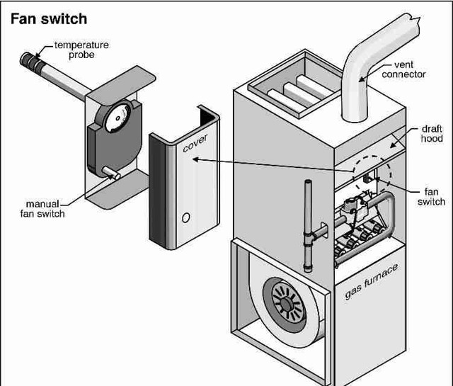
The main purpose of the switch
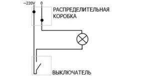 The task of the device is to close or open the electrical circuit, thereby including the lighting device
A light switch is a device for switching conductors that connects and disconnects an electrical wiring circuit. Standard models are connected to a circuit with certain parameters. The characteristics of the mechanisms and wiring must match, otherwise short circuits and other problems will occur.
Switches are designed for specific load voltage and conducted current limits. You can specify the parameters of the device in the technical instructions or look at the case. The main task of the switch is to supply power to the lamp and stop the supply if the lighting fixture is not needed. Modern types of switches differ significantly from each other in many ways.
The principle of operation and features of toggle switches
To understand the principle of operation of a cross-type toggle switch, it is necessary to study the control scheme for lighting points from 3-5 points.
But since the cross switch is always installed between the walk-through switches and is never used by itself, you first need to understand how the lighting activation and deactivation circuit works with conventional and walk-through switches.
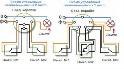 Three-point lighting control circuits differ from a two-way circuit only in the presence of a cross switch
So, the functions of a conventional switch include opening and closing the circuit - when the upper half of the key is pressed, the light turns on, the bottom half turns off. But the state of lighting in a circuit with two pass-through devices is completely independent of the position of the keys of one of them.


Pressing the key only switches the connection from one circuit to another.For the circuit to close, it is necessary that both devices make contact with one of the conductors laid between them.
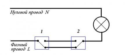 A pass switch is also called a two-way switch. The diagram clearly demonstrates that the user, using any of them, will be able to turn the light on and off.
The mechanism of different types of devices differs in the number of terminals:
- in the usual two;
- in the transition there are three;
- in the cross - four terminals.
The more complex the device, the more it requires better manufacturing. Therefore, the design of toggle switches, which have a large number of terminals, is distinguished by high strength, wear resistance, and corrosion resistance.
Most models have a high level of protection (IP) from negative external factors - dust, moisture.
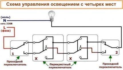 If pass-through switches are always used only in pairs, then the number of toggle switches can be any - at least one, at least ten
Like feedthrough switches, crossover switches switch connections from one conductor to another. But their difference lies in the fact that there are already two input contacts, not one, and their switching also needs to be controlled. The principle of operation of the device is based on the pair switching of contacts.
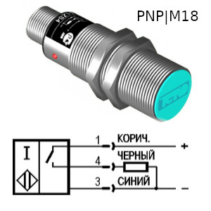
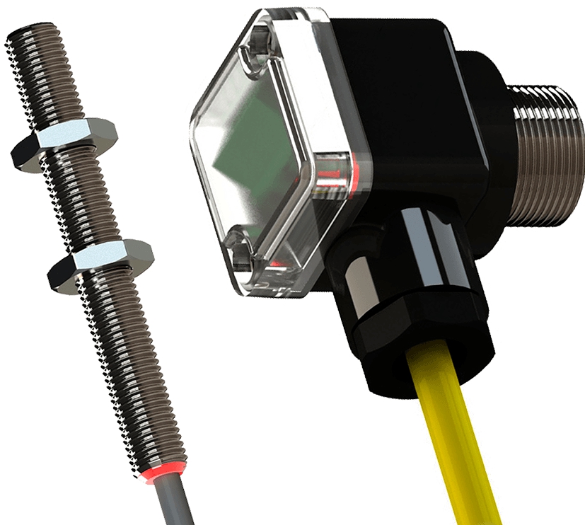
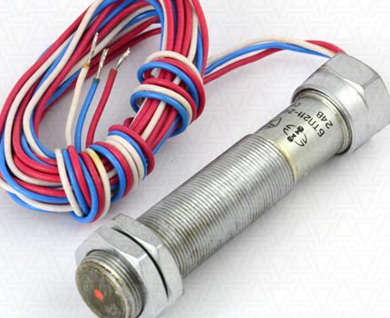
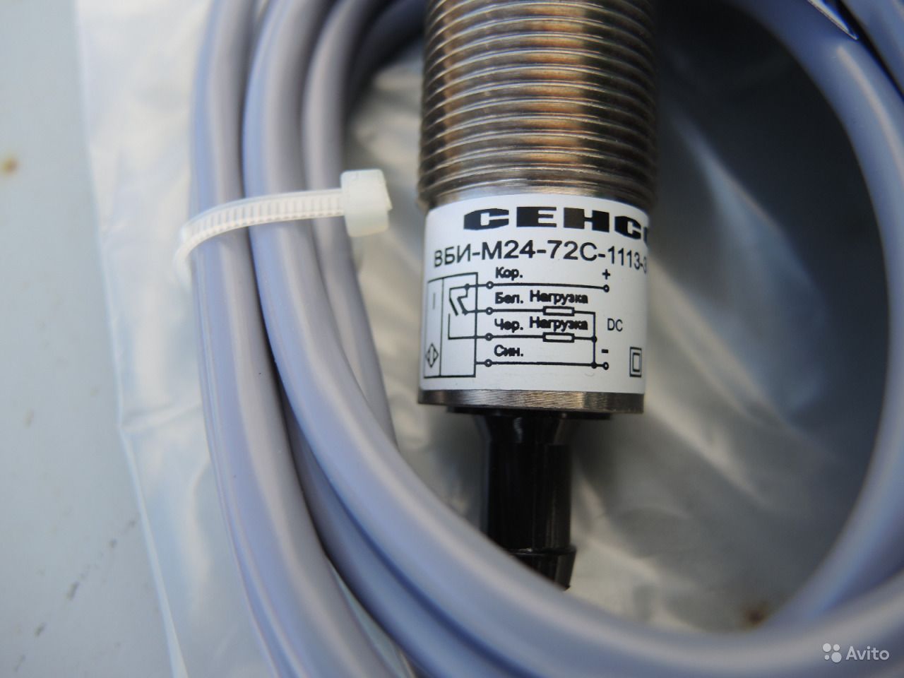
Limit switch KV-04
The design of the KV-04 (two-position, single-channel, rotary) is basically similar to the previous devices. Unlike a single-position switch, it is complicated by the presence of a rotary lever, with which you can adjust the angle of rotation of the axis in the direction and counterclockwise. Thus, the reed switches are switched.
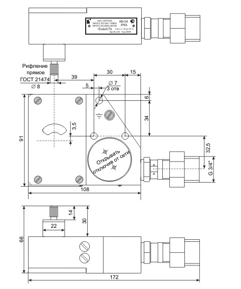
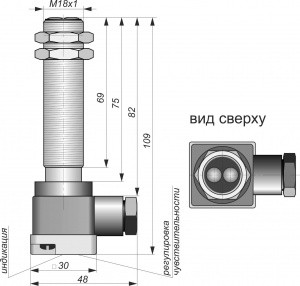
Rice. No. 4.Dimensional drawing of the switch KV-04
The adjustment takes place by changing the cams located on the washer, they act on the levers, when turned, the magnet moves, switching the reed switch.
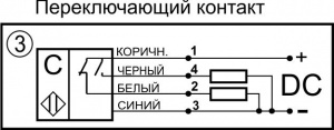
Fig. No. 5. Schematic diagram of connection of the limit switch KV-04.
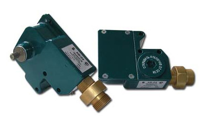
Rice. No. 6. A photo limit switch KV-04.
Kinds
There are one-, two- and three-pole devices. The first two are designed for a load of 10-25 A, the allowable voltage is 220V. Three-pole devices can withstand a voltage of 380 V, while the load is somewhat reduced, it should not be more than 15 A.
Available in open, closed and fully sealed bags. There is no protective sheath in open-type circuit breakers. These packets are used to switch connections at safe voltage and indoors only. Closed devices are equipped with a plastic or metal housing. The terminals of these devices are closed from touch, and the device itself is perfectly protected from dirt and dust. Closed models are allowed to be installed outside the shield cabinet.
Sealed electrical appliances are enclosed in a non-combustible, shockproof, sealed plastic shell. A high level of protection allows you to mount devices in an open space. Some models are equipped with a transparent window through which you can monitor the status of contacts.


The popularity of package devices is gradually decreasing, but the production of such electrical appliances has not been stopped. Reliability, availability, and quick response help bags to remain in demand.
Advantages and disadvantages
For comparison, let's take electromagnetic relays with coils and a core. In addition, here are some general positive and negative qualities.
pros
- The dimensions of reed switches are much smaller due to the lack of mechanics for moving the contacts and the core itself.
- Most of the technical characteristics, such as, for example, electrical strength, breakdown voltage are several orders of magnitude higher than those of electromagnetic relays.
- The speed of reed switches significantly exceeds that of conventional relays.
- During operation, there is no noise characteristic of the operation of electromagnetic relays.
- The service life of reed switches many times exceeds the durability of electromagnetic relays.
- Reed switches do not require coordination to the type of load.
- To control an electromagnetic relay, electricity is required; reed switches can be controlled without using it.
Minuses
- The switched load has low power ratings.
- A small number of contacts are placed in the flask.
- In a dry reed switch, the closing process is accompanied by contact bounce. Wet reed switches are spared from this technical phenomenon.
- The reed switch is large for compact modern electronic circuits.
- The glass flask does not have sufficient strength, it can collapse from vibrational phenomena that occur in the operation of equipment with reed switches.
- A protective screen is required to eliminate the influence of external magnetic fields on the normal functioning of the reed switch.
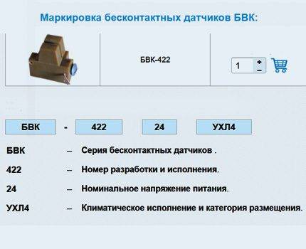
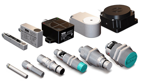
Who manufactures limit switches
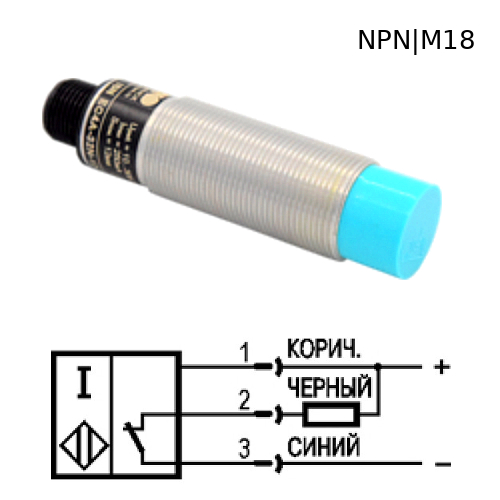
Many companies produce such sensors. Among them there are recognized leaders. Among them is the German company Sick, as the main manufacturer of such high quality products. Autonics supplies the market with inductive and capacitive limit switches.
High quality non-contact sensors are produced by the Russian company "TEKO". They feature ultra-high tightness (IP 68). These limit switches work in the most dangerous environments, including explosive ones, various mounting methods are available.
The limit switches of the Ukrainian manufacturer Promfactor are popular. Here they produce switches and limit switches VP, PP, VU. The warranty, subject to all operating rules, is 3 years.
Device and principle of operation
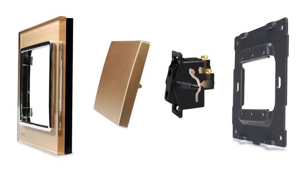
Structurally, a single-key switch consists of four main parts:
- bases (metal, less often plastic);
- working mechanism, consisting of a contact group, clamps (for connecting electrical wires) and fastening elements;
- keys;
- protective decorative element (frame or case).
The principle of operation of any single-gang switch is extremely simple:
- In the "on" position, the elements of the contact group are closed and the voltage is supplied to the lighting device. It starts to function.
- And vice versa, in the “off” position, the contacts are disconnected, a “break” occurs in the “phase” circuit, and the lamp goes out.
Voltage
230/400V - inscriptions of the rated voltage where this machine can be used.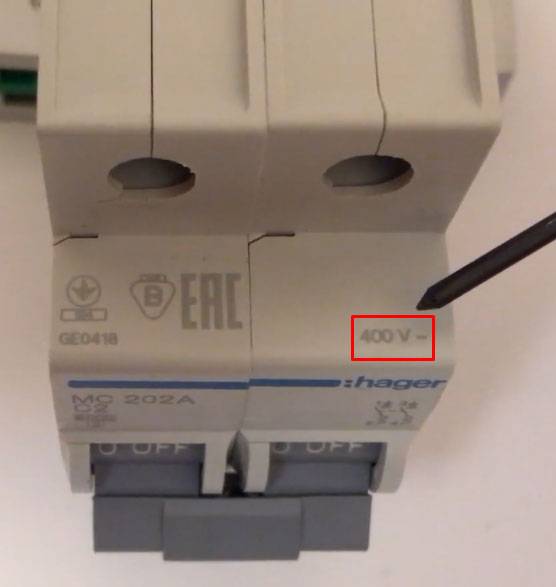
If there is a 230V icon (without 400V), these devices should only be used in single-phase networks. You can't put two or three single-phase switches in a row and supply 380V to a motor load or a three-phase pump or fan in this way.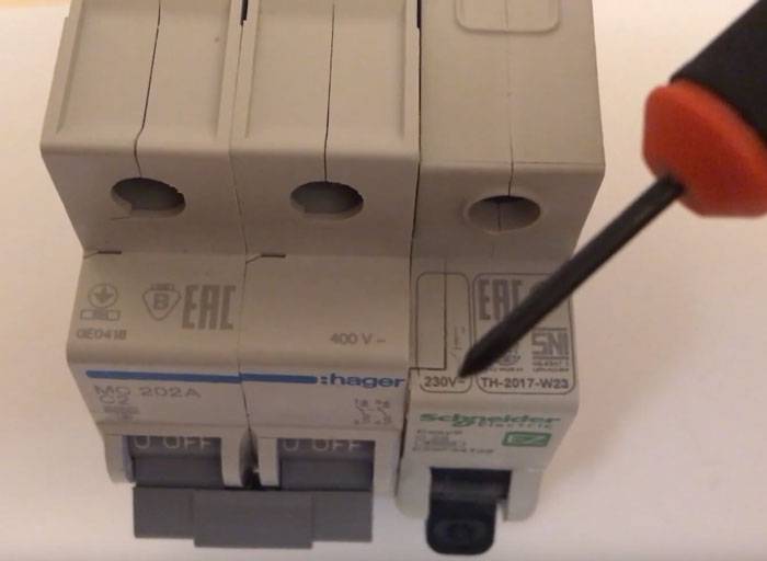
Also carefully study the bipolar models. If they have the letter “N” written on one of the poles (not only difavtomatov), then it is here that the zero core is connected, and not the phase one.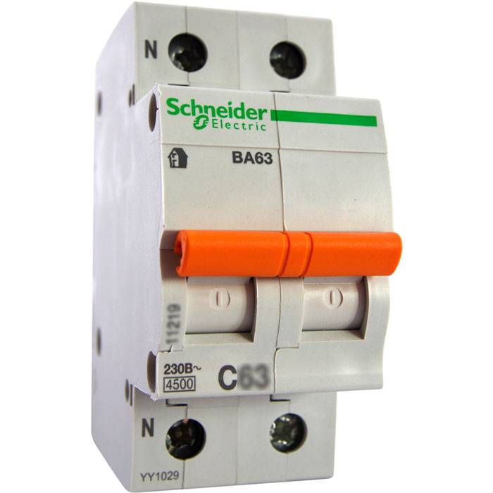
They are called somewhat differently. For example VA63 1P+N.
The wave icon means - for operation in alternating voltage networks.
For direct voltage and current, it is better not to install such devices. The characteristics of its shutdown and the result of work during a short circuit will not be predictable.
Switches for direct current and voltage, in addition to the icon in the form of a straight line, may have characteristic inscriptions “+” (plus) and “-” (minus) on their terminals.
Moreover, the correct connection of the poles is critical here. This is due to the fact that the conditions for extinguishing the arc at direct current are somewhat more difficult.
If at a break there is a natural extinction of the arc when the sinusoid passes through zero, then at a constant, there is no sinusoid as such. For stable arc extinguishing, a magnet is used in them, which is installed near the arc chute.
Which will lead to the inevitable destruction of the hull.
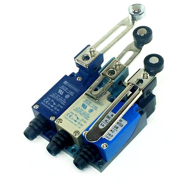
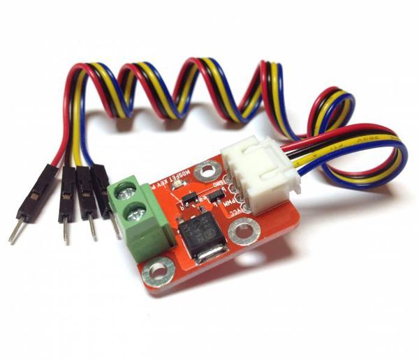
Mechanical type limit switches
The control of this type of limit switches is roller or lever. They work as soon as the control mechanism in the form of a wheel, button or lever is subjected to mechanical action. In this case, the position of the contacts changes - they can close or open. The process is accompanied by a signal - control or warning.


Most often, limit switches have two contacts - open and closed. There are single end devices, but they are rare. In any case, there are contacts in each case, and the working diagram with their numbers is shown on the panel.
The design of roller VC provides for switching off by pressing the actuator on a button in the form of a small rod. Since it is associated with dynamic contacts, at the moment of contact, the supply circuit is opened.
The difference between lever switches is that their movable contacts are connected by means of a rod or through a stem to a small lever. Action occurs when the actuator presses this lever.
The photo shows a mechanical limit switch KW4-3Z-3 with a push plate. It differs from the standard stroke of the working element. It is used in CNC machines, 3D printers
In addition to standard end devices, there are microswitches. They work on the same principle, but their adjustment during installation requires more accuracy due to the small stroke. To increase the working stroke, they resort to such a technique as inclusion in the circuit of an intermediate element - lever with roller.
This type of switch is used both in production and at home. The design of the elevator used a large number of KU. Among them is a switch in the form of a sensor that limits the minimum and maximum height of the lift, signals a rope break, gives a signal to open the door and performs many more actions. There are microswitches on the doors in many apartments that turn on the light in the room when it is opened.
Features of automotive limit switches
In automobiles, such mechanical end sensors are included in signaling and lighting circuits. Their feature is the presence of one input with a positive potential connected to it. The housing is a negative terminal pressed against a metal element on the car body, free from paint.
This element is connected to the vehicle ground by a cable. The main condition is that the switch should not come into contact with a wet surface.Connect the end sensors when installing a car alarm using the diagram. Their outputs can be installed both on the doors and in the cabin on the lighting fixtures.
To turn on when the door is opened, and turn off when it is closed, a short to positive is performed. In the presence of illumination of the ceiling of the cabin and doors, a block of limit switches is used that performs various functions. As a result of the operation of the block, important sensors are blocked when trying to open the locks.
Deciding on a denomination
Actually, from the functions of the circuit breaker, the rule for determining the rating of the circuit breaker follows: it must operate until the current exceeds the wiring capabilities. And this means that the current rating of the machine must be less than the maximum current that the wiring can withstand.
For each line, you need to choose the right circuit breaker
Based on this, the algorithm for choosing a circuit breaker is simple:
- Calculate the cross section of the wiring for a specific area.
- See what maximum current this cable can withstand (there is in the table).
- Further, from all the denominations of circuit breakers, we select the nearest smaller one. The ratings of the machines are tied to the permissible continuous load currents for a particular cable - they have a slightly lower rating (there is in the table). The list of ratings looks like this: 16 A, 25 A, 32 A, 40 A, 63 A. From this list, choose the right one. There are denominations and less, but they are practically not used anymore - we have too many electrical appliances and they have considerable power.
Example
The algorithm is very simple, but it works flawlessly. To make it clearer, let's look at an example.Below is a table that indicates the maximum allowable current for conductors that are used when laying wiring in a house and apartment. There are also recommendations regarding the use of machines. They are given in the column "Rated current of the circuit breaker". It is there that we are looking for denominations - it is slightly less than the maximum allowable, so that the wiring works in normal mode.
| Cross section of copper wires | Permissible continuous load current | Maximum load power for a single-phase network 220 V | Rated current of the circuit breaker | Circuit breaker current limit | Approximate load for a single-phase circuit |
|---|---|---|---|---|---|
| 1.5 sq. mm | 19 A | 4.1 kW | 10 A | 16 A | lighting and signaling |
| 2.5 sq. mm | 27 A | 5.9 kW | 16 A | 25 A | socket groups and electric underfloor heating |
| 4 sq. mm | 38 A | 8.3 kW | 25 A | 32 A | air conditioners and water heaters |
| 6 sq. mm | 46 A | 10.1 kW | 32 A | 40 A | electric stoves and ovens |
| 10 sq. mm | 70 A | 15.4 kW | 50 A | 63 A | introductory lines |
In the table we find the selected wire section for this line. Suppose we need to lay a cable with a cross section of 2.5 mm² (the most common when laying to medium power devices). A conductor with such a cross section can withstand a current of 27 A, and the recommended rating of the machine is 16 A.
How will the chain work then? As long as the current does not exceed 25 A, the machine does not turn off, everything works in normal mode - the conductor heats up, but not to critical values. When the load current begins to increase and exceeds 25 A, the machine does not turn off for some time - perhaps these are starting currents and they are short-lived. It turns off if the current exceeds 25 A by 13% for a sufficiently long time. In this case, if it reaches 28.25 A.Then the electropacket will work, de-energize the branch, since this current already poses a threat to the conductor and its insulation.
Power calculation
Is it possible to choose an automatic machine according to the load power? If only one device is connected to the power line (usually it is a large household appliance with a large power consumption), then it is permissible to make a calculation based on the power of this equipment. Also in terms of power, you can choose an introductory machine, which is installed at the entrance to a house or apartment.
If we are looking for the value of the introductory machine, it is necessary to add up the power of all devices that will be connected to the home network. Then the found total power is substituted into the formula, the operating current for this load is found.
Formula for calculating current from total power
After we have found the current, select the value. It can be either a little more or a little less than the found value. The main thing is that its tripping current does not exceed the maximum allowable current for this wiring.


When can this method be used? If the wiring is laid with a large margin (this is not bad, by the way). Then, in order to save money, you can install automatically switches corresponding to the load, and not to the cross section of the conductors
But once again we pay attention that the long-term permissible current for the load must be greater than the limiting current of the circuit breaker. Only then the choice of automatic protection will be correct
Varieties
Devices are classified into the following groups.
By the nature of the action
- Normally open contact. Under the influence of a magnetic field of a certain intensity, the contacts are closed, and a current flows through the circuit. After the end of the action, the elastic forces return them to their place.
- Normally closed contact.The external magnetic field must form such a strength that the resulting repulsive force overcomes the elasticity of the contact pair.
- Switched contacts. The variant has three contacts for connection: two are made of magnetic material, and one is not magnetic. The first two are mutually attracted and commute one of the electrical circuits. In the absence of magnetic fields, the magnetic contacts (one of them) are switched to non-magnetic and the circuit is re-switched.
By type of construction
- Dry. This is a reed switch with a vacuum bulb and contacts in an inert gas environment. When closing, contact bounce is not excluded (uncontrolled presence or absence of contact between their elastic working surfaces).
- Wet. In such devices, a drop of liquid metal, mercury, is added to the contacts. With elastic vibrations during the closing of the contacts, it fills the space between them and does not allow the electrical circuit to break.
Varieties
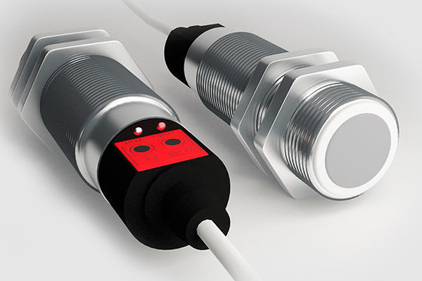
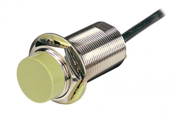
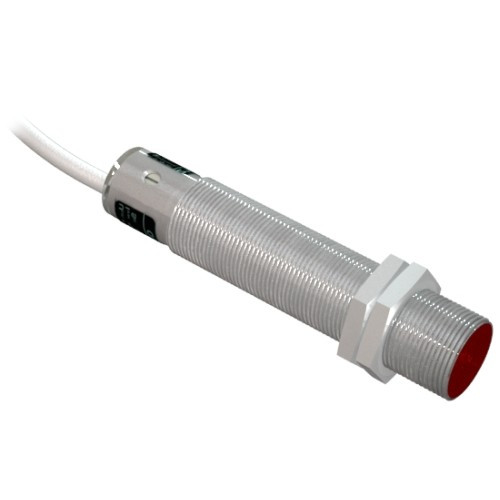
It is important to know what limit switches are, because without this knowledge it will be difficult to choose the right device. These switching devices are divided into several main types:
- Contactless. This device is triggered in the event of the approach of any metal or other object to which switching has been made in advance.
- Mechanical. They work only with mechanical action on the wheel or on the lever. As a result, the contacts either close or open, thereby giving a control or warning signal.
- Magnetic. They are also called reed switches.Based on the name, it can be understood that the device is triggered when a magnet approaches it at a certain distance.
Non-contact limit switches are more modern than mechanical ones. They work on a special transistor key, which in the open position has a small resistance.
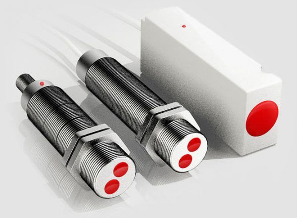
All proximity switches are divided into four groups:
- Inductive. The limit switch is triggered when the sensor detects a metal object. At the moment of metal detection, the inductive reactance increases, due to this, the current in the winding decreases, and thus the contacts in the circuit open. The range of these products is very large and diverse, so you can easily choose the right size.
- Capacitive, interact with the human body. When a person approaches the sensor, an electrical capacitance arises, due to which the circuit of the multivibrator installed inside the device is put into operation. The closer the person is, the lower the pulse frequency becomes, and the capacitance becomes larger. The main function is performed by the plate, which is attached to the capacitor.
- Ultrasonic. Quartz sound emitting elements are used. When something appears within the range of the device, the amplitude of the sound signal changes, basically this purity is inaudible to people.
- Optical switches have a special transistor and an infrared LED. When the LED beam is interrupted, the photocell closes.
The video below shows some types of limit switches:
Scheme of connecting the limit switch to the starter
Limit switches are mainly used in industrial, household automation, as well as in electrical products.In terms of their functions, the devices are similar to a conventional switch, there are differences only in constructiveness. All types of such sensors act on the motor of any drive, as well as the starter and lighting circuits.
The limit switch is called the limit switch, which is installed in the control system for generating a signal that gives permission for the further operation of the circuit. It usually has several pairs of contacts (open and closed). But there are also contactless limit switches, which consist of an infrared LED and a photocell located opposite each other.
Lighting with cross switch in TN-S network
Connecting a cross switch in the TN-S electrical network, which is characterized by the separation of the working (N) and protective (PE) zero, has some nuances. Unlike the old, not entirely safe TN-C system, the electrical network, carried out according to the new standards, uses 3 cores when applying single-phase voltage, and 5 when three-phase.
The wire that performs the function of zero (N, marked in blue) comes out of the electrical panel, passes through the junction box and connects to the zero of the lamp. The ground wire (PE, denoted in yellow-green) is connected to the ground wire of the lighting fixture.
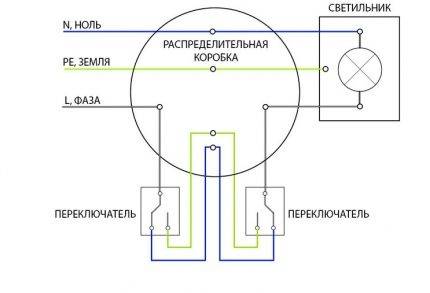 Laying electrical networks through the TN-S system significantly increases the cost of materials, but reduces the risks associated with the operation of electrical equipment
Machine marking
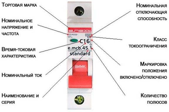
Circuit breaker marking
Each machine has its own marking, which is an alphanumeric and conditional graphic images used to identify and communicate to the consumer its main technical characteristics.They are necessary for the correct selection and further operation of the machine.


- manufacturer's name or trademark;
- type designation, catalog number or series number;
- the value of the rated voltage;
- rated current values without the symbol "A" with the preceding designation of the type of protective characteristic (A, B, C, D, K, Z) and the current limiting class;
- nominal frequency value;
- the value of the rated shortest breaking capacity in amperes;
- connection diagram, if the correct connection method is not obvious;
- the value of the control temperature of the ambient air, if it differs from 30 °C;
- degree of protection, if only it differs from IP20;
- for type D circuit breakers, the maximum value of the instantaneous tripping current if it is higher than 20In;
- value of the rated impulse withstand voltage Uimp.
The labeling of difavtomatov is similar to the labeling of AB, but contains additional information:
- rated breaking differential current;
- tripping differential current settings (for DV with several values of tripping differential current);
- rated maximum differential making and breaking capacity;
- a button with the symbol "T" for operational control of the operability of the DV by differential current;
- symbol "~" - for DV type AC;
- symbol for DV type A.
Deciphering the designations of circuit breakers
Along with the marking of the switches, the necessary information about the characteristics and type of AB contains its symbol, which is required to place an order for the purchase of AB.
The symbol of the circuit breaker has the following form: VA47-X1-X2X3X4XX5-UHL3
Explanations for the symbol AB are given in the table.
| Symbol | Decryption |
| BA47 | Switch series designation |
| X1 | Breaker type |
| X2 | Number of poles |
| X3 | The letter "N" in the presence of a pole without a release |
| X4 | Type of protection characteristic |
| XX5 | Rated operational current |
| UHL3 | Designation of climatic version and placement category (according to GOST 15150) |
Examples of notation AB:
- single-pole automatic switch with a protective characteristic of type "C" for a rated current of 16 A: Switch VA47-29-1S16-UHL3
- four-pole automatic switch with a protective characteristic of type "C" with an unprotected pole for a rated current of 100 A: Switch VA47-100-4NC100-UHL3.
For UHL3 products, the operating temperature range is from minus 60 to +40 °C.


