- The purpose of the purification of fossil fuel
- Four options for cleaning with alkonolamines
- Existing installations
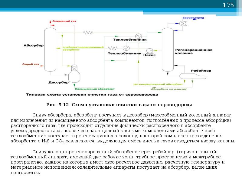
- Operating principle of a typical installation
- Technology system
- Absorber
- Separation and heating of saturated amine
- Desorber
- Filtration system
- Membrane method of gas purification
- Chemisorption gas cleaning
- Gas cleaning with alkanolamine solutions
- Alkaline (carbonate) methods of gas purification
- Purpose
- Advantages and disadvantages
- Advantages
- Flaws
- The choice of absorbent for the cleaning process
- Process chemistry
- Basic reactions
- Adverse reactions
- The main advantages of the membrane from NPK "Grasys" and the scope of its application
- Conclusions and useful video on the topic
The purpose of the purification of fossil fuel
Gas is the most popular type of fuel. It attracts with the most affordable price and causing the least damage to the environment. The undeniable advantages include the ease of controlling the combustion process and the ability to secure all stages of fuel processing in the course of obtaining thermal energy.
However, the natural gaseous fossil is not mined in its pure form, because. associated organic compounds are pumped out simultaneously with the extraction of gas from the well.The most common of them is hydrogen sulfide, the content of which varies from tenths to ten or more percent, depending on the deposit.
Hydrogen sulfide is poisonous, hazardous to the environment, harmful to catalysts used in gas processing. As we have already noted, this organic compound is extremely aggressive towards steel pipes and metal valves.
Naturally, corroding the private system and the main gas pipeline with corrosion, hydrogen sulfide leads to leakage of blue fuel and extremely negative, risky situations associated with this fact. To protect the consumer, compounds harmful to health are removed from the composition of gaseous fuel even before it is delivered to the highway.
According to the standards of hydrogen sulfide compounds in the gas transported through pipes, it cannot be more than 0.02 g / m³. However, in fact, there are much more of them. In order to achieve the value regulated by GOST 5542-2014, cleaning is required.
Four options for cleaning with alkonolamines
Alkonolamines or amino alcohols are substances containing not only an amine group, but also a hydroxy group.
The design of installations and technologies for purifying natural gas with alkanolamines differ mainly in the way the absorbent is supplied. Most often, four main methods are used in gas cleaning using this type of amines.
First way. Predetermines the supply of the active solution in one stream from above. The entire volume of the absorbent is sent to the top plate of the unit. The cleaning process takes place at a temperature background not higher than 40ºС.
The simplest cleaning method involves the supply of the active solution in one stream.This technique is used if there is a small amount of impurities in the gas
This technique is usually used for minor contamination with hydrogen sulfide compounds and carbon dioxide. In this case, the total thermal effect for obtaining commercial gas is, as a rule, low.
The second way. This cleaning option is used when the content of hydrogen sulfide compounds in gaseous fuel is high.
The reactive solution in this case is fed into two streams. The first, with a volume of approximately 65-75% of the total mass, is sent to the middle of the installation, the second is delivered from above.
The amine solution flows down the trays and meets the ascending gas streams, which are forced onto the bottom tray of the absorber. Before serving, the solution is heated to no more than 40ºС, but during the interaction of the gas with the amine, the temperature rises significantly.
So that the cleaning efficiency does not decrease due to the increase in temperature, the excess heat is removed together with the waste solution saturated with hydrogen sulfide. And at the top of the installation, the flow is cooled in order to extract the remaining acidic components along with the condensate.
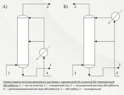 The second and third of the methods described predetermine the supply of the absorbent solution in two streams. In the first case, the reagent is served at the same temperature, in the second - at different temperatures.
This is an economical way to reduce the consumption of both energy and active solution. Additional heating is not carried out at any stage. Technologically, it is a two-level purification, which provides an opportunity to prepare marketable gas for supply to the pipeline with the least losses.
The third way. It involves the supply of the absorber to the cleaning plant in two streams of different temperatures.The technique is applied if, in addition to hydrogen sulfide and carbon dioxide, there is also CS in the raw gas2, and COS.
The predominant part of the absorber, approximately 70-75%, is heated to 60-70ºС, and the remaining share is only up to 40ºС. Streams are fed into the absorber in the same way as in the case described above: from above and into the middle.

The formation of a zone with a high temperature makes it possible to quickly and efficiently extract organic contaminants from the gas mass at the bottom of the purification column. And at the top, carbon dioxide and hydrogen sulfide are precipitated by an amine of standard temperature.
Fourth way. This technology predetermines the supply of an aqueous solution of amine in two streams with different degrees of regeneration. That is, one is supplied in an unpurified form, with the content of hydrogen sulfide inclusions, the second - without them.
The first stream cannot be called completely polluted. It only partially contains acidic components, because some of them are removed during cooling to +50º/+60ºС in the heat exchanger. This solution stream is taken from the bottom nozzle of the desorber, cooled and sent to the middle part of the column.
With a significant content of hydrogen sulfide and carbon dioxide components in gaseous fuel, cleaning is carried out with two streams of solution with different degrees of regeneration
Deep cleaning passes only that part of the solution, which is injected into the upper sector of the installation. The temperature of this stream usually does not exceed 50ºС. Fine cleaning of gaseous fuel is carried out here. This scheme allows you to reduce costs by at least 10% by reducing steam consumption.
It is clear that the cleaning method is chosen based on the presence of organic contaminants and economic feasibility. In any case, a variety of technologies allows you to choose the best option.On the same amine gas treatment plant, it is possible to vary the degree of purification, obtaining blue fuel with the characteristics necessary for the operation of gas boilers, stoves, and heaters.
Existing installations
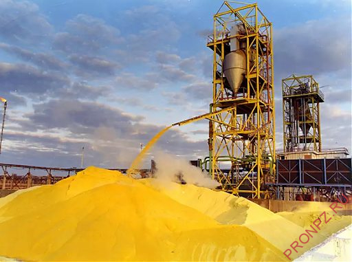
At present, the main sulfur producers are gas processing plants (GPPs), oil refineries (ORs) and petrochemical complexes (OGCC). Sulfur at these enterprises is produced from acid gases formed during the amine treatment of high-sulfur hydrocarbon feedstock. The vast majority of gaseous sulfur is produced by the well-known Claus method.
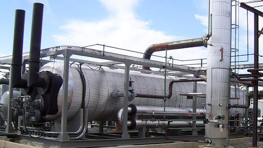
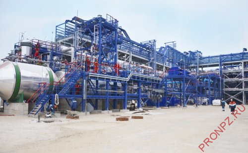 Sulfur production plant. Orsk refinery
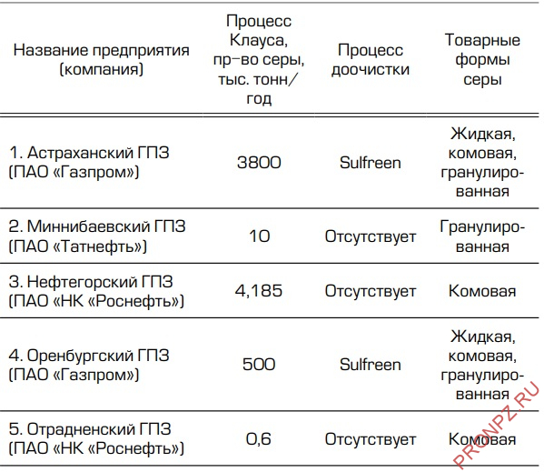
From the data presented in Tables 1–3, it can be seen what types of commercial sulfur are produced today by Russian enterprises that produce sulfur.
Table 1 - Russian refineries producing sulfur

Table 2 - Russian oil and gas chemical complexes producing sulfur

Table 3 - Russian gas processing plants producing sulfur
Operating principle of a typical installation
Maximum absorption capacity with respect to H2S is characterized by a solution of monoethanolamine. However, this reagent has a couple of significant drawbacks. It is distinguished by a rather high pressure and the ability to create irreversible compounds with carbon sulphide during the operation of the amine gas treatment plant.
The first minus is eliminated by washing, as a result of which the amine vapor is partially absorbed. The second one is rarely encountered during the processing of field gases.
The concentration of an aqueous solution of monoethanolamine is selected empirically, on the basis of the studies carried out, it is taken to purify gas from a certain field.In selecting the percentage of the reagent, its ability to withstand the aggressive effects of hydrogen sulfide on the metal components of the system is taken into account.


The standard content of the absorbent is usually in the range from 15 to 20%. However, it often happens that the concentration is increased to 30% or reduced to 10%, depending on how high the degree of purification should be. Those. for what purpose, in heating or in the production of polymer compounds, gas will be used.
Note that with an increase in the concentration of amine compounds, the corrosivity of hydrogen sulfide decreases. But it must be taken into account that in this case the consumption of the reagent increases. Consequently, the cost of purified commercial gas increases.
The main unit of the cleaning plant is the absorber of the plate-shaped or mounted type. This is a vertically oriented, externally resembling test tube apparatus with nozzles or plates located inside. In its lower part there is an inlet for the supply of an untreated gas mixture, at the top there is an outlet to the scrubber.
If the gas to be purified in the plant is under pressure sufficient to allow the reagent to pass into the heat exchanger and then into the stripping column, the process occurs without the participation of a pump. If the pressure is not enough for the flow of the process, the outflow is stimulated by pumping technology
The gas stream after passing through the inlet separator is injected into the lower section of the absorber. Then it passes through plates or nozzles located in the middle of the body, on which contaminants settle. The nozzles, completely moistened with an amine solution, are separated from each other by gratings for uniform distribution of the reagent.
Further, the blue fuel purified from pollution is sent to the scrubber.This device can be connected in the processing circuit after the absorber or located in its upper part.
The spent solution flows down the walls of the absorber and is sent to a stripping column - a desorber with a boiler. There, the solution is cleaned of absorbed contaminants with vapors released when water is boiled to return back to the installation.
Regenerated, i.e. rid of hydrogen sulfide compounds, the solution flows into the heat exchanger. In it, the liquid is cooled in the process of transferring heat to the next portion of the contaminated solution, after which it is pumped into the refrigerator by a pump for full cooling and steam condensation.
The cooled absorbent solution is fed back into the absorber. This is how the reagent circulates through the plant. Its vapors are also cooled and cleaned of acidic impurities, after which they replenish the supply of the reagent.
Most often, schemes with monoethanolamine and diethanolamine are used in gas purification. These reagents make it possible to extract from the composition of blue fuel not only hydrogen sulfide, but also carbon dioxide
If it is necessary to simultaneously remove CO from the treated gas2 and H2S, two-stage cleaning is performed. It consists in the use of two solutions that differ in concentration. This option is more economical than single-stage cleaning.
First, gaseous fuel is cleaned with a strong composition with a reagent content of 25-35%. Then the gas is treated with a weak aqueous solution, in which the active substance is only 5-12%. As a result, both coarse and fine cleaning are performed with a minimum consumption of solution and a reasonable use of the generated heat.
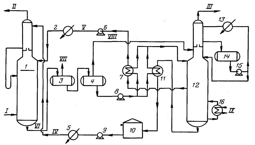
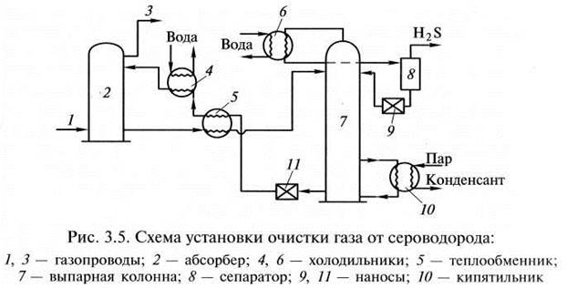
Technology system
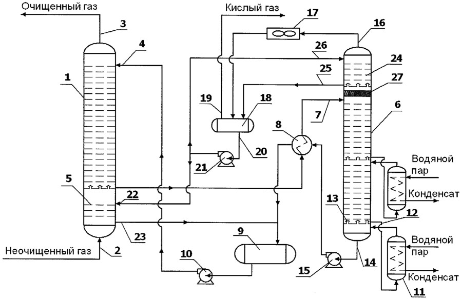
 Schematic representation of a typical process equipment for acid gas treatment with a regenerative absorbent
Absorber
Acid gas supplied for purification enters the lower part of the absorber. This apparatus typically contains 20 to 24 trays, but for smaller installations it may be a packed column. The aqueous amine solution enters the top of the absorber. As the solution flows down the trays, it is in contact with the acid gas as the gas moves up through the liquid layer on each tray. When the gas reaches the top of the vessel, almost all of the H2S and, depending on the absorbent used, all CO2 removed from the gas stream. Purified gas meets specifications for H content2S, CO2, common sulfur.
Separation and heating of saturated amine
The saturated amine solution leaves the absorber at the bottom and passes through the pressure relief valve, providing a pressure drop of approximately 4 kgf/cm2. After depressurization, the enriched solution enters the separator, where most of the dissolved hydrocarbon gas and some acid gas are released. The solution then flows through a heat exchanger, heated by the heat of the hot regenerated amine stream.
Desorber
The saturated absorbent enters the apparatus, where the absorbent is regenerated at a pressure of about 0.8-1 kgf/cm2 and the boiling point of the solution. Heat is supplied from an external source such as a reboiler.Stripped sour gas and any hydrocarbon gas not vaporized in the separator exits at the top of the stripper along with a small amount of absorbent and a large amount of steam. This vapor stream passes through a condenser, usually an air cooler, to condense the absorbent and water vapors.
The mixture of liquid and gas enters a separator, commonly referred to as a reflux tank (reflux accumulator), where the acid gas is separated from the condensed liquids. The liquid phase of the separator is fed back to the top of the desorber as reflux. A gas stream consisting mainly of H2S and CO2, is usually sent to the sulfur recovery unit. The regenerated solution flows from the reboiler through the saturated / regenerated amine solution heat exchanger to the air cooler and then to the expansion tank. The stream is then pumped back to the top of the absorber by a high pressure pump to continue scrubbing the acid gas.
Filtration system
Most absorbent systems have a means of filtering the solution. This is achieved by passing a saturated amine solution from the separator through a particulate filter and sometimes through a carbon filter. The aim is to maintain a high degree of purity of the solution to avoid foaming of the solution. Some absorbent systems also have means to remove decomposition products, which include maintaining an additional reboiler for this purpose when regeneration equipment is connected.


Membrane method of gas purification
Currently, one of the most technologically advanced methods of gas desulfurization is membrane.This cleaning method allows not only to get rid of acidic impurities, but also to simultaneously dry, strip the feed gas and remove inert components from it. Membrane gas desulfurization is used when it is not possible to remove sulfur emissions using more traditional methods.
Membrane gas desulfurization technology does not require significant capital investments, as well as impressive installation costs. These devices are cheaper both to use and maintain. The main advantages of membrane gas desulfurization include:
- no moving parts. Thanks to this feature, the installation works remotely and automatically, without human intervention;
- efficient layout ensures minimization of weight and area, which makes these devices very popular on offshore platforms;
- the design, thought out to the smallest detail, allows to carry out desulfurization and release hydrocarbons to the maximum extent possible;
- membrane desulfurization of gases provides regulated parameters of the commercial product;
- ease of installation work. The whole complex is installed on one frame, which allows it to be included in the technological scheme in just a couple of hours.
Chemisorption gas cleaning
The main advantage of chemisorption processes is a high and reliable degree of gas purification from acidic components with low absorption of hydrocarbon components of the feed gas.
Caustic sodium and potassium, alkali metal carbonates, and most widely alkanolamines are used as chemisorbents.
Gas cleaning with alkanolamine solutions
Amine processes have been used in industry since 1930, when the scheme of the amine plant with phenylhydrazine as an absorbent was first developed and patented in the USA.
The process has been improved by using aqueous solutions of alkanolamines as scavengers. Alkanolamines, being weak bases, react with acid gases H2S and CO2, due to which the gas is purified. The resulting salts easily decompose when the saturated solution is heated.
The best known ethanolamines used in gas purification processes from H2S and CO2 are: monoethanolamine (MEA), diethanolamine (DEA), triethanolamine (TEA), diglycolamine (DGA), diisopropanolamine (DIPA), methyldiethanolamine (MDEA).
So far, in industry, in acid gas treatment plants, monoethanolamine (MEA) and also diethanolamine (DEA) have been mainly used as an absorbent. However, in recent years there has been a trend to replace MEA with a more effective absorbent, methyldiethanolamine (MDEA).
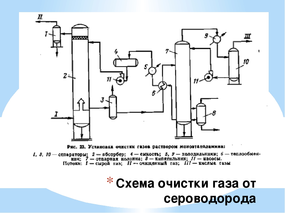
The figure shows the main single-flow scheme of absorption gas cleaning with ethanolamine solutions. The gas supplied for purification passes in an upward flow through the absorber towards the flow of the solution. The solution saturated with acid gases from the bottom of the absorber is heated in the heat exchanger by the regenerated solution from the desorber and fed to the top of the desorber.
After partial cooling in the heat exchanger, the regenerated solution is additionally cooled with water or air and fed to the top of the absorber.
The acid gas from the stripper is cooled to condense water vapor. The reflux condensate is continuously returned to the system to maintain the desired concentration of the amine solution.
Alkaline (carbonate) methods of gas purification
The use of amine solutions for cleaning gases with a low content of H2S (less than 0.5% vol.) and high CO2 to H2S is considered irrational, since the content of H2S in regeneration gases is 3–5% vol. It is almost impossible to obtain sulfur from such gases in typical plants, and they have to be flared, which leads to atmospheric pollution.
For purification of gases containing small amounts of H2S and CO2, alkaline (carbonate) cleaning methods are used in industry. The use of alkali solutions (carbonates) as an absorbent increases the concentration of H2S in regeneration gases and simplifies the layout of sulfur or sulfuric acid plants.
The industrial process of alkaline purification of natural gas has the following advantages:
- fine purification of gas from the main sulfur-containing compounds;
- high selectivity to hydrogen sulfide in the presence of carbon dioxide;
- high reactivity and chemical resistance of the absorber;
- availability and low cost of the absorber;
- low operating costs.
The use of alkaline gas cleaning methods is also advisable in field conditions for cleaning small amounts of feed gas and with a small content of H in the gas.2S.
Purpose
Sulfur production units convert H2S contained in acid gas streams from amine recovery plants and sour-alkaline effluent neutralization plants into liquid sulfur. Typically a two or three step Claus process recovers over 92% H2S as elemental sulfur.
Most refineries require more than 98.5% sulfur recovery, so the third Claus stage operates below the sulfur dew point. The third stage may contain a selective oxidation catalyst, otherwise the sulfur production unit must include a tail gas afterburner. It is becoming increasingly popular to degas the resulting molten sulfur. Large companies offer proprietary processes that degas molten sulfur to 10-20 wt. ppm H2S.


Advantages and disadvantages
Advantages
- Simplicity of technological design of the installation.
- Removal of H2S from combustion gases, which allows compliance with the environmental standards of the enterprise.
 Pipeline corrosion at a sulfur recovery plant
Flaws
- Unintentional condensation and accumulation of sulfur can lead to problems such as obstruction of the process gas flow, plugging with solid sulfur, fire and equipment damage.
- Excess supply of sulfur on the market over its demand.
- Corrosion and contamination of equipment due to the presence of ammonia, H2S, CO2 possible formation of sulfuric acid.
The choice of absorbent for the cleaning process
The desired characteristics of the absorbent are:
- the need to remove hydrogen sulfide H2S and other sulfur compounds.
- absorption of hydrocarbons should be low.
- The vapor pressure of the absorbent must be low to minimize absorbent loss.
- reactions between solvent and acid gases must be reversible to prevent degradation of the absorbent.
- the absorbent must be thermally stable.
- removal of degradation products should be simple.
- acid gas uptake per unit of circulating absorbent should be high.
- the heat requirement for regeneration or removal of the absorbent should be low.
- the absorbent must be non-corrosive.
- the absorbent must not foam in the absorber or desorber.
- selective removal of acid gases is desirable.
- the absorbent must be cheap and readily available.
Unfortunately, there is no single absorbent that has all the desired characteristics. This necessitates the selection of an absorbent that is best suited to treat a particular acid gas mixture from the various available absorbents. Sour natural gas blends vary in:
- content and ratio of H2S and CO2
- content of heavy or aromatic compounds
- content COS, CS2 and mercaptans
While sour gas is primarily treated with absorbents, for mild acid gas it may be more economical to use absorbent absorbents or solid agents. In such processes, the compound chemically reacts with H2S and is consumed during the cleaning process, requiring periodic replacement of the cleaning component.
Process chemistry
Basic reactions
The process consists of a multi-stage catalytic oxidation of hydrogen sulfide according to the following general reaction:
2H2S+O2 → 2S+2H2O
The Claus process involves burning one third of the H2S with air in a reactor furnace to form sulfur dioxide (SO2) according to the following reaction:
2H2S+3O2 → 2SO2+2H2O
The remaining unburned two-thirds of the hydrogen sulfide undergoes a Claus reaction (reaction with SO2) to form elemental sulfur as follows:
2H2S+SO2 ←→ 3S + 2H2O
Adverse reactions
Generation of hydrogen gas:
2H2S→S2 + 2H2
CH4 + 2H2O→CO2 + 4H2
Formation of carbonyl sulfide:
H2S+CO2 → S=C=O + H2O
Formation of carbon disulfide:
CH4 + 2S2 → S=C=S + 2H2S
The main advantages of the membrane from NPK "Grasys" and the scope of its application
The Grasys gas desulfurization method avoids unnecessary financial costs. An innovative product differs from analogues:
- hollow fiber configuration;
- a fundamentally new sequence of the velocity component of the penetration of the components of the gas mixture;
- increased chemical resistance to most components of the hydrocarbon stream;
- excellent selectivity.
In the technological process of preparing natural and associated petroleum gas, all impurities to be removed are concentrated in a low-grade stream, while the purified gas that meets the regulated standards exits with almost the same pressure as at the inlet.
The main purpose of the hydrocarbon membrane developed by our company is the desulfurization of gases. But these are far from all the applications of our innovative product. With it, you can:


- solve many environmental problems by eliminating gas flaring, that is, reducing to zero harmful emissions that pollute the environment;
- prepare, dry and utilize gas directly at production facilities;
- ensure complete independence of devices from transport schemes, infrastructure facilities, as well as from energy carriers. The resulting gas can be used as fuel in gas turbine power plants, boiler houses, as well as for heating change houses. There is no need to spend imported coal for water heating and space heating, if there is gas;
- remove sulfur, dry and prepare gas for supply to main gas pipelines (standards STO Gazprom 089-2010);
- save material resources as a result of optimization of technological processes.
RPC "Grasys" can offer each Customer an optimal engineering solution for the task, taking into account the parameters of the incoming feed gas flows, the requirements for the degree of desulfurization, the dew point for water and hydrocarbons, the volume of the commercial product and its component composition.
Conclusions and useful video on the topic
The following video will acquaint you with the specifics of the extraction of hydrogen sulfide from associated gas produced along with oil by an oil well:
The installation for the purification of blue fuel from hydrogen sulfide with the production of elemental sulfur for further processing will be presented by the video:
The author of this video will tell you how to get rid of biogas from hydrogen sulfide at home:
The choice of gas purification method is primarily focused on solving a specific problem. The performer has two paths: to follow a proven pattern or to prefer something new. However, the main guideline should still be economic feasibility while maintaining quality and obtaining the desired degree of processing.